Linear vibration motor

a linear vibration and motor technology, applied in mechanical vibration separation, dynamo-electric machines, electrical apparatus, etc., can solve the problems of reducing the damping function, affecting the damping effect, and affecting the operation life of the motor, so as to increase the magnetic flux of the magnet

Inactive Publication Date: 2013-02-07
SAMSUNG ELECTRO MECHANICS CO LTD
View PDF9 Cites 34 Cited by
  • Summary
  • Abstract
  • Description
  • Claims
  • Application Information

AI Technical Summary

Benefits of technology

[0023]The vibrator part may further include a cylindrical yoke coupled between the coil and the weight body and increasing a magnetic flux of the magnet, and the elastic member may have one end coupled to the stator part and the other end coupled to the coil and the weight body through the cylindrical yoke.

Problems solved by technology

First, as the number of vibration generation according to the touch becomes larger than that of vibration generation at the time of call reception, an operation lifespan time needs to increase.
In the case of the linear vibration motor configured as described above, as the vibrator part moves vertically, it collides with a case or a bracket to thereby cause touch noise.
However, when the MF is used, the MF is made of liquid to be scattered to the surroundings at the time of excessive impact, such that it is separated from its position.
Therefore, a damping function is weakened, such that noise is generated at the time of a vibration operation.
In addition, the damping material such as the rubber, the Poron, or the like, occupies a predetermined volume, such that it may not be easily disposed in a limited space and a degree of freedom in design is degraded.

Method used


Image

  • Linear vibration motor
  • Linear vibration motor
  • Linear vibration motor

Examples


Embodiment Construction

[0037]Various objects, advantages and features of the invention will become apparent from the following description of embodiments with reference to the accompanying drawings. In the specification, in adding reference numerals to components throughout the drawings, it is to be noted that like reference numerals designate like components even though components are shown in different drawings. Further, terms used in the specification, ‘first’, ‘second’, etc. can be used to describe various components, but the components are not to be construed as being limited to the terms. The terms are only used to differentiate one component from other components. Further, when it is determined that the detailed description of the known art related to the present invention may obscure the gist of the present invention, the detailed description thereof will be omitted.

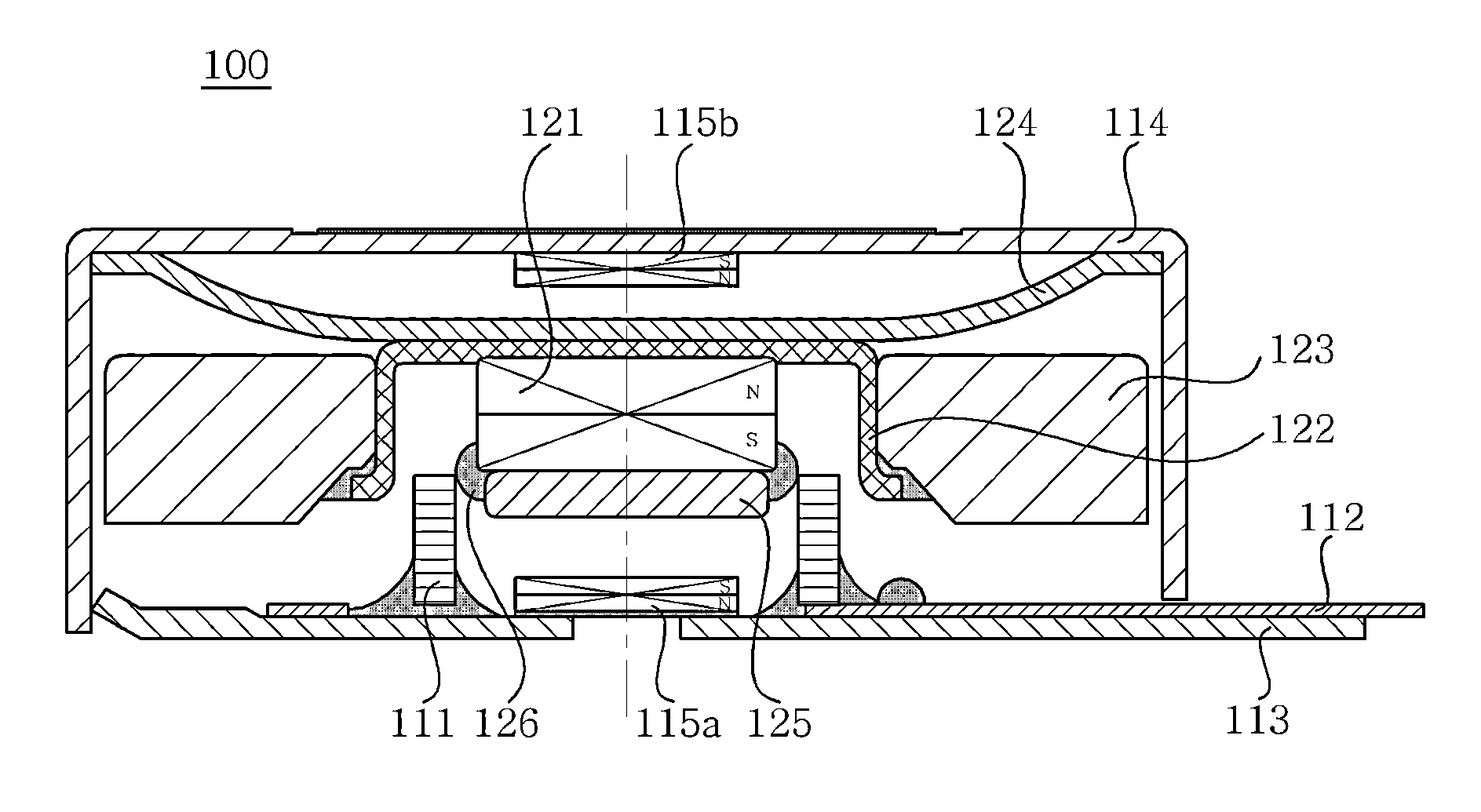
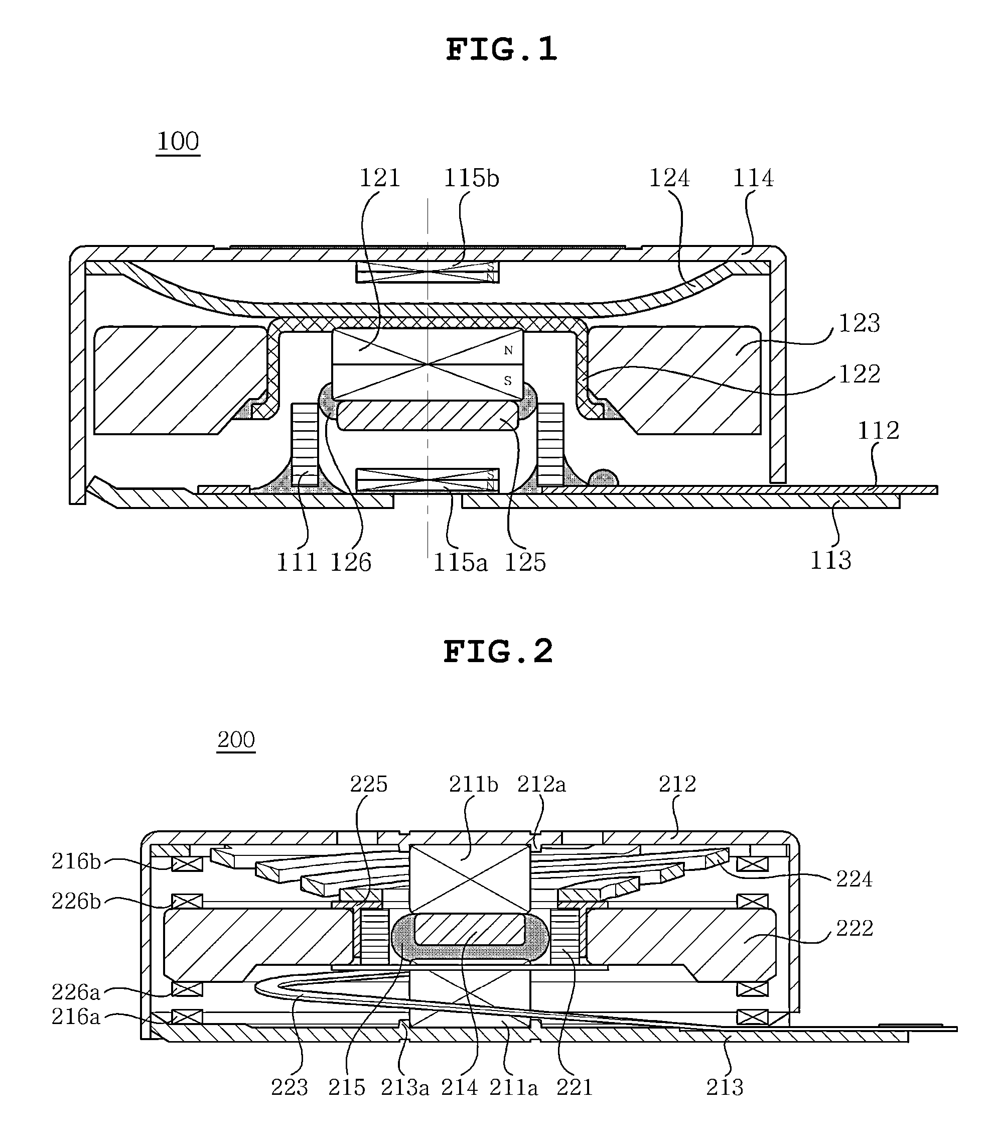
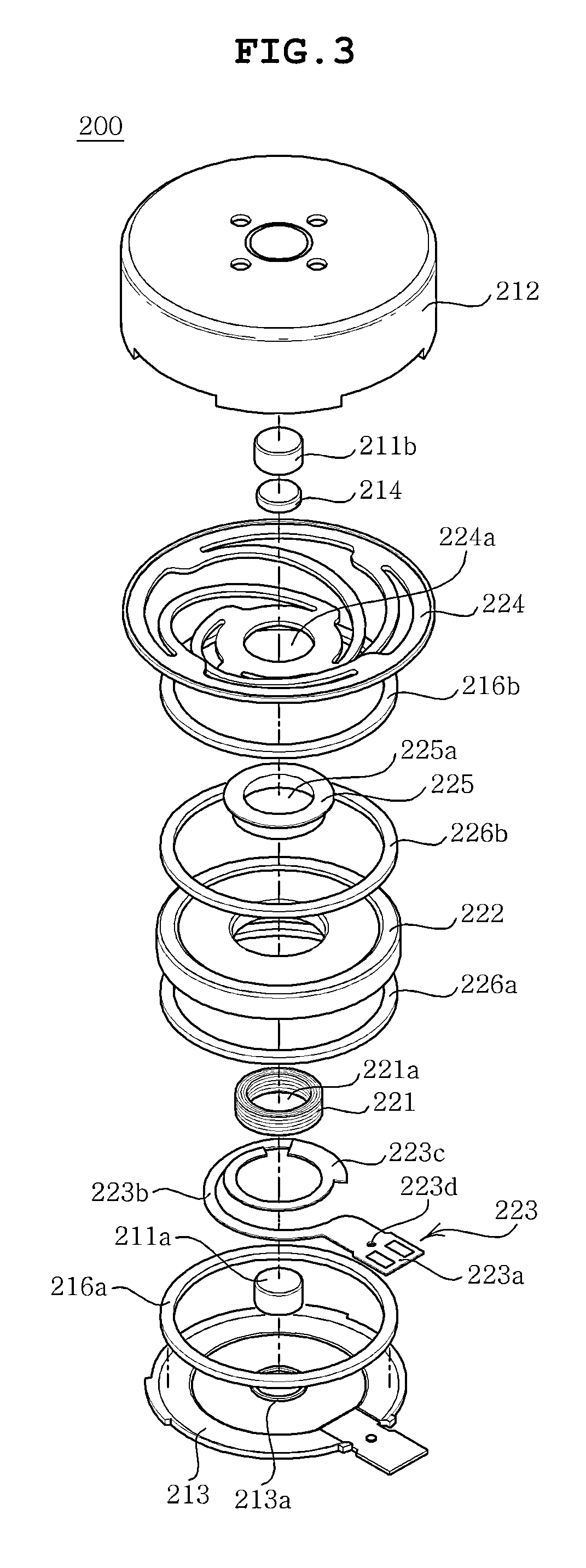
[0038]Hereinafter, a linear vibration motor according to preferred embodiments of the present invention will be described in detail w...


PUM


Abstract

Disclosed herein is a linear vibration motor including: a stator part including a coil, a printed circuit board coupled to the coil, a bracket having the printed circuit board fixedly coupled thereto, and a case having an internal space formed therein and coupled to the bracket; and a vibrator part including a main magnet positioned to face the coil, a yoke coupled to the magnet, a weight body coupled to an outer peripheral surface of the yoke, and an elastic member having one end coupled to the case and the other end coupled to the yoke, wherein the stator part further includes sub-magnets, which are magnetic damping units, the sub-magnets being disposed to face the main magnet of the vibrator part and being mounted in the stator part so that surfaces thereof facing the main magnet have the same polarities as those of the main magnet.

Description

CROSS REFERENCE TO RELATED APPLICATION[0001]This application claims the benefit of Korean Patent Application No. 10-2011-0077883, filed on Aug. 4, 2011, entitled “Linear Motor”, which is hereby incorporated by reference in its entirety into this application.BACKGROUND OF THE INVENTION[0002]1. Technical Field[0003]The present invention relates to a linear vibration motor.[0004]2. Description of the Related Art[0005]A general vibration motor, which is a component converting an electrical energy into mechanical vibration using a principle of generating electromagnetic force, is mounted in a mobile communication terminal, a portable terminal, and the like, to be used for silently notifying a user of call reception.[0006]Further, in a situation in which small-sized and high quality components are required in a mobile communication terminal in accordance with the trend in which a multi-functional mobile communication terminal has been prominent due to the rapid expansion in wireless commu...

Claims


Application Information

Patent Timeline
Patent Type & Authority Applications(United States)
IPC IPC(8): H02K33/00
CPCH02K33/16B06B1/045H02K33/18H02K33/02H02K41/02
Inventor YOON, AN SOO
Owner SAMSUNG ELECTRO MECHANICS CO LTD
Why Eureka
Try Eureka