Current-perpendicular-to-the-plane (CPP) magnetoresistive (MR) sensor with magnetic damping material at the sensor edges

a technology of magnetic damping material and sensor edge, which is applied in the field of current perpendicular to the plane (cpp) giant magnetoresistive (gmr) sensors, can solve the problems of limiting the bias current at which the sensors can operate, substantial low-frequency magnetic noise in the measured electrical resistance, and prone to current-induced noise and instability. , to achieve the effect of reducing the effect of spin transfer torqu

Active Publication Date: 2013-11-05
WESTERN DIGITAL TECH INC
View PDF17 Cites 12 Cited by
  • Summary
  • Abstract
  • Description
  • Claims
  • Application Information

AI Technical Summary

Benefits of technology

[0008]The invention relates to CPP sensors with magnetic damping material to reduce the effect of spin transfer torque (STT). Magnetic damping material is located adjacent either or both of the sensor side edges and back edge. The damping material may be platinum (Pt), palladium (Pd), osmium (Os), or a rare earth metal from the 15 lanthanoid (formerly called “lanthanide”) elements. The damping material may be an ultrathin layer in contact with the sensor edges. An insulating layer is deposited on the damping layer and isolates the sensor's ferromagnetic biasing layer from the damping layer. The damping layer is

Problems solved by technology

CPP-GMR sensors are susceptible to current-induced noise and instability.
This can produce magnetic instabilities and even continuous gyrations of the magnetization in the ferromagnetic layers, resulting in substantial low-frequency magnetic noise in the measured electrical resistance if the bias current is above a certain level.
However, the adverse effect of STT limits the bias current at which the sensors can operate.

Method used


Image

  • Current-perpendicular-to-the-plane (CPP) magnetoresistive (MR) sensor with magnetic damping material at the sensor edges
  • Current-perpendicular-to-the-plane (CPP) magnetoresistive (MR) sensor with magnetic damping material at the sensor edges
  • Current-perpendicular-to-the-plane (CPP) magnetoresistive (MR) sensor with magnetic damping material at the sensor edges

Examples


Embodiment Construction

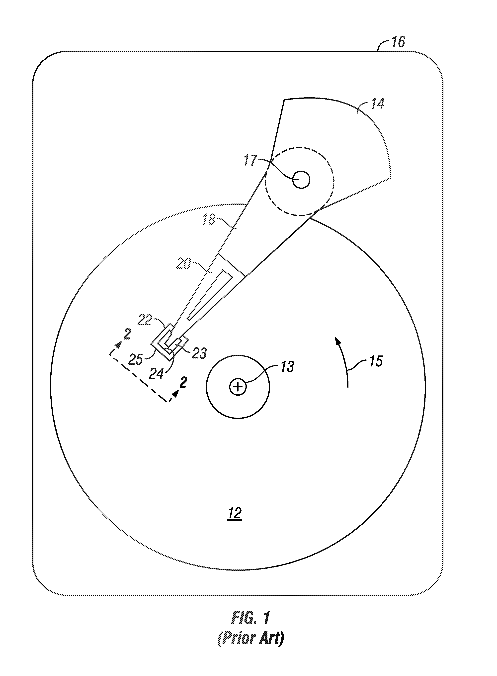
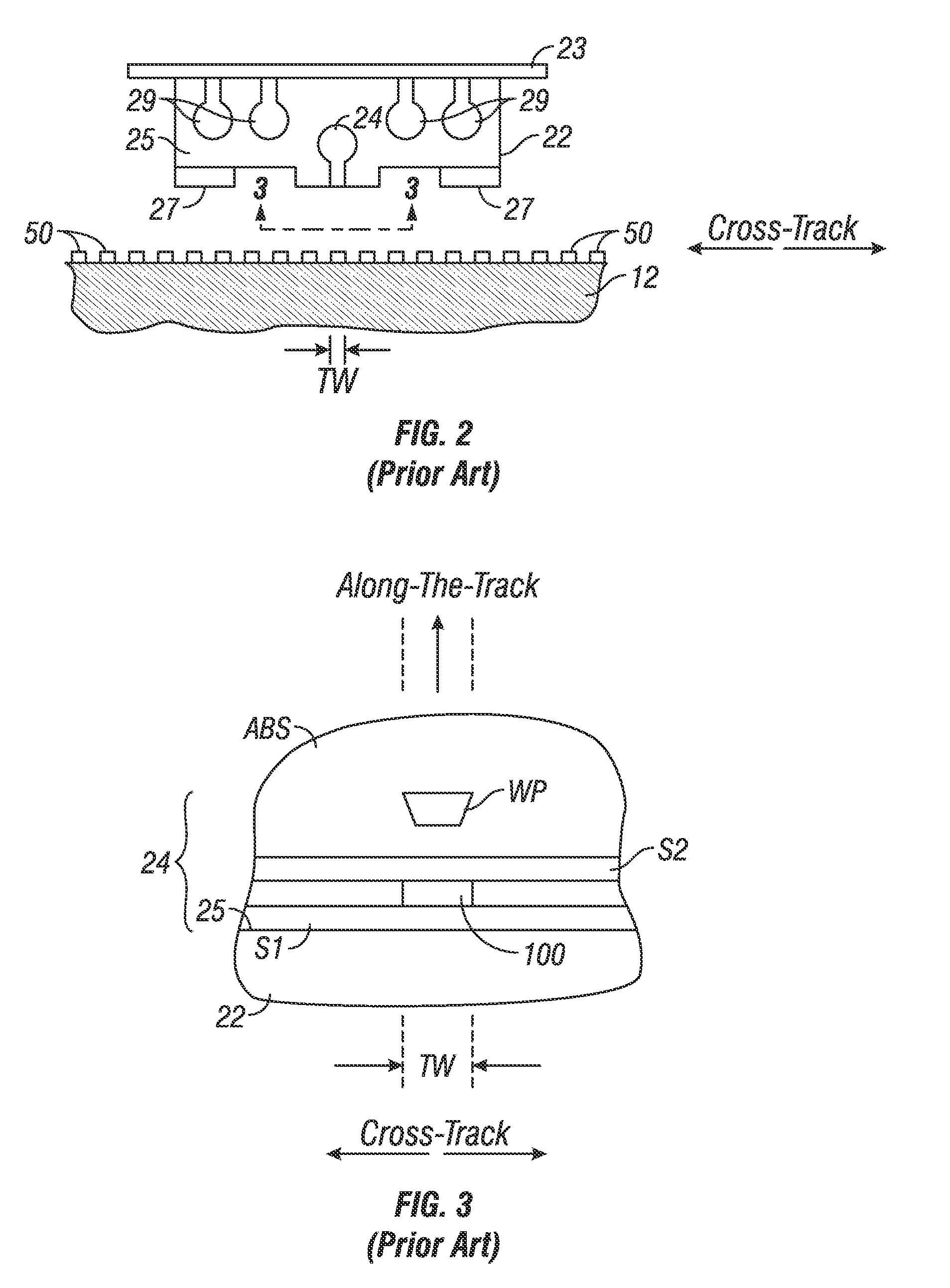
[0016]The CPP giant magnetoresistive (GMR) sensor of this invention has application for use in a magnetic recording disk drive, the operation of which will be briefly described with reference to FIGS. 1-3. FIG. 1 is a block diagram of a conventional magnetic recording hard disk drive. The disk drive includes a magnetic recording disk 12 and a rotary voice coil motor (VCM) actuator 14 supported on a disk drive housing or base 16. The disk 12 has a center of rotation 13 and is rotated in direction 15 by a spindle motor (not shown) mounted to base 16. The actuator 14 pivots about axis 17 and includes a rigid actuator arm 18. A generally flexible suspension 20 includes a flexure element 23 and is attached to the end of arm 18. A head carrier or air-bearing slider 22 is attached to the flexure 23. A magnetic recording read / write head 24 is formed on the trailing surface 25 of slider 22. The flexure 23 and suspension 20 enable the slider to “pitch” and “roll” on an air-bearing generated b...


PUM


Abstract

A current-perpendicular-to-the-plane magnetoresistive sensor has magnetic damping material located adjacent either or both of the sensor side edges and back edge to reduce the effect of spin transfer torque. The damping material may be Pt, Pd, Os, or a rare earth metal from the 15 lanthanoid elements. The damping material may be an ultrathin layer in contact with the sensor edges. An insulating layer is deposited on the damping layer and isolates the sensor's ferromagnetic biasing layer from the damping layer. Instead of being a separate layer, the damping material may be formed adjacent the sensor edges by being incorporated into the material of the insulating layer.

Description

BACKGROUND OF THE INVENTION[0001]1. Field of the Invention[0002]The invention relates generally to a current-perpendicular-to-the-plane (CPP) giant magnetoresistive (GMR) sensor that operates with the sense current directed perpendicularly to the planes of the layers making up the sensor stack, and more particularly to a CPP-GMR sensor with magnetic damping to suppress spin transfer torque (STT).[0003]2. Background of the Invention[0004]One type of conventional magnetoresistive (MR) sensor used as the read head in magnetic recording disk drives is a “spin-valve” sensor based on the giant magnetoresistance (GMR) effect. A GMR spin-valve sensor has a stack of layers that includes two ferromagnetic layers separated by a nonmagnetic electrically conductive spacer layer, which is typically copper (Cu) or silver (Ag). One ferromagnetic layer adjacent the spacer layer has its magnetization direction fixed, such as by being pinned by exchange coupling with an adjacent antiferromagnetic laye...

Claims


Application Information

Patent Timeline
IPC IPC(8): G11B5/39
CPCG11B5/3929G11B5/3932G11B5/398G01R33/093G01R33/098H01L43/08H01F10/329H01F10/123H01F10/3272H10N50/10
Inventor CAREY, MATTHEW J.CHILDRESS, JEFFREY R.CHOI, YOUNG-SUKREAD, JOHN CREIGHTON
Owner WESTERN DIGITAL TECH INC
Why Eureka
Try Eureka