
Spindle motor

a spindle motor and spindle technology, applied in the direction of magnetic circuit rotating parts, magnetic circuit shape/form/construction, instruments, etc., can solve the problems of increasing the manufacturing cost of the motor, and achieve the effect of improving the rotational characteristics, and increasing the bearing span length

Inactive Publication Date: 2013-02-07
SAMSUNG ELECTRO MECHANICS CO LTD
View PDF11 Cites 13 Cited by
  • Summary
  • Abstract
  • Description
  • Claims
  • Application Information

AI Technical Summary

Benefits of technology

The present invention provides a spindle motor with improved rotational characteristics by increasing bearing span length and suppressing deterioration in coupling strength between a shaft and a thrust member. This is achieved by using a spindle motor with an upper thrust member, a sleeve, and a rotor hub coupled together, and a cover member fixedly coupled to the shaft, wherein the upper thrust member includes a stepped jaw part or a step part formed in the upper end portion of the shaft to increase coupling strength with the upper thrust member or the shaft, respectively. This results in a more robust and efficient spindle motor for rotating a rotary shaft.

Problems solved by technology

Since a large number of components are required in order to configure the hydrodynamic bearing assembly as described above, a manufacturing cost thereof increases.

Method used


Image

  • Spindle motor
  • Spindle motor
  • Spindle motor

Examples


Embodiment Construction

[0027]Embodiments of the present invention will now be described in detail with reference to the accompanying drawings. However, it should be noted that the spirit of the present invention is not limited to the embodiments set forth herein and those skilled in the art and understanding the present invention can easily accomplish retrogressive inventions or other embodiments included in the spirit of the present invention by the addition, modification, and removal of components within the same spirit, but those are construed as being included in the spirit of the present invention.

[0028]Further, when it is determined that the detailed description of the known art related to the present invention may obscure the gist of the present invention, the detailed description thereof will be omitted.

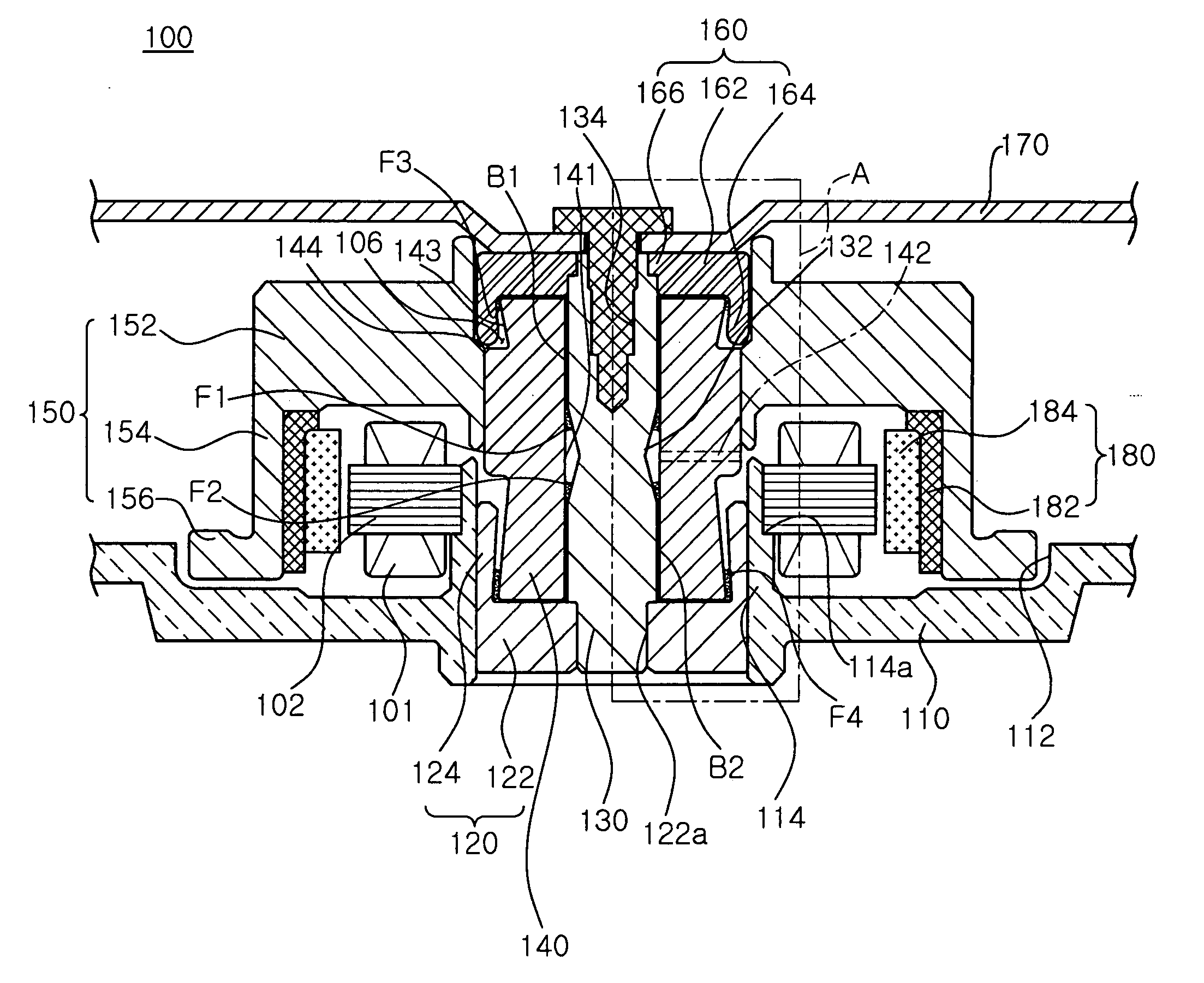
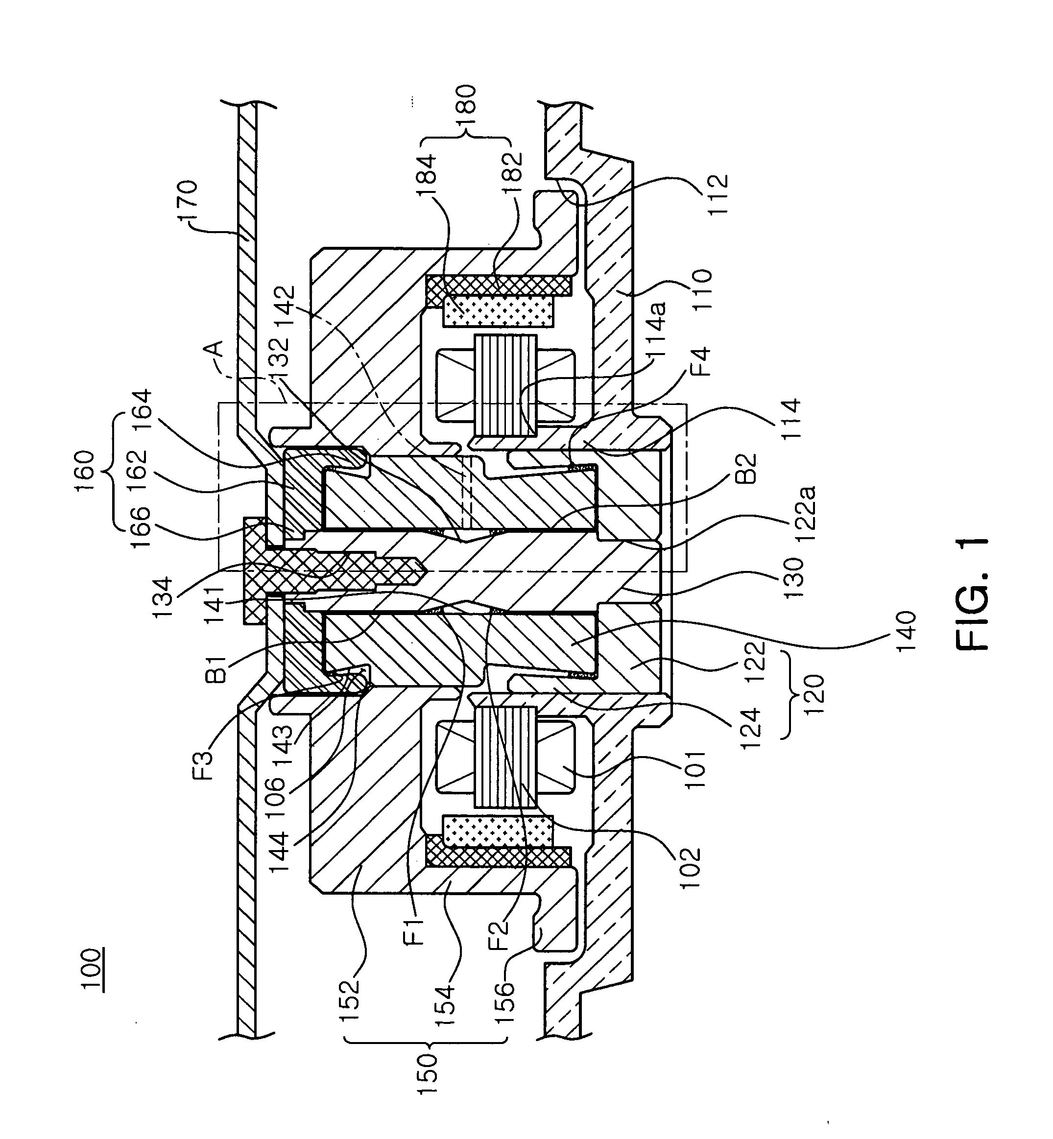
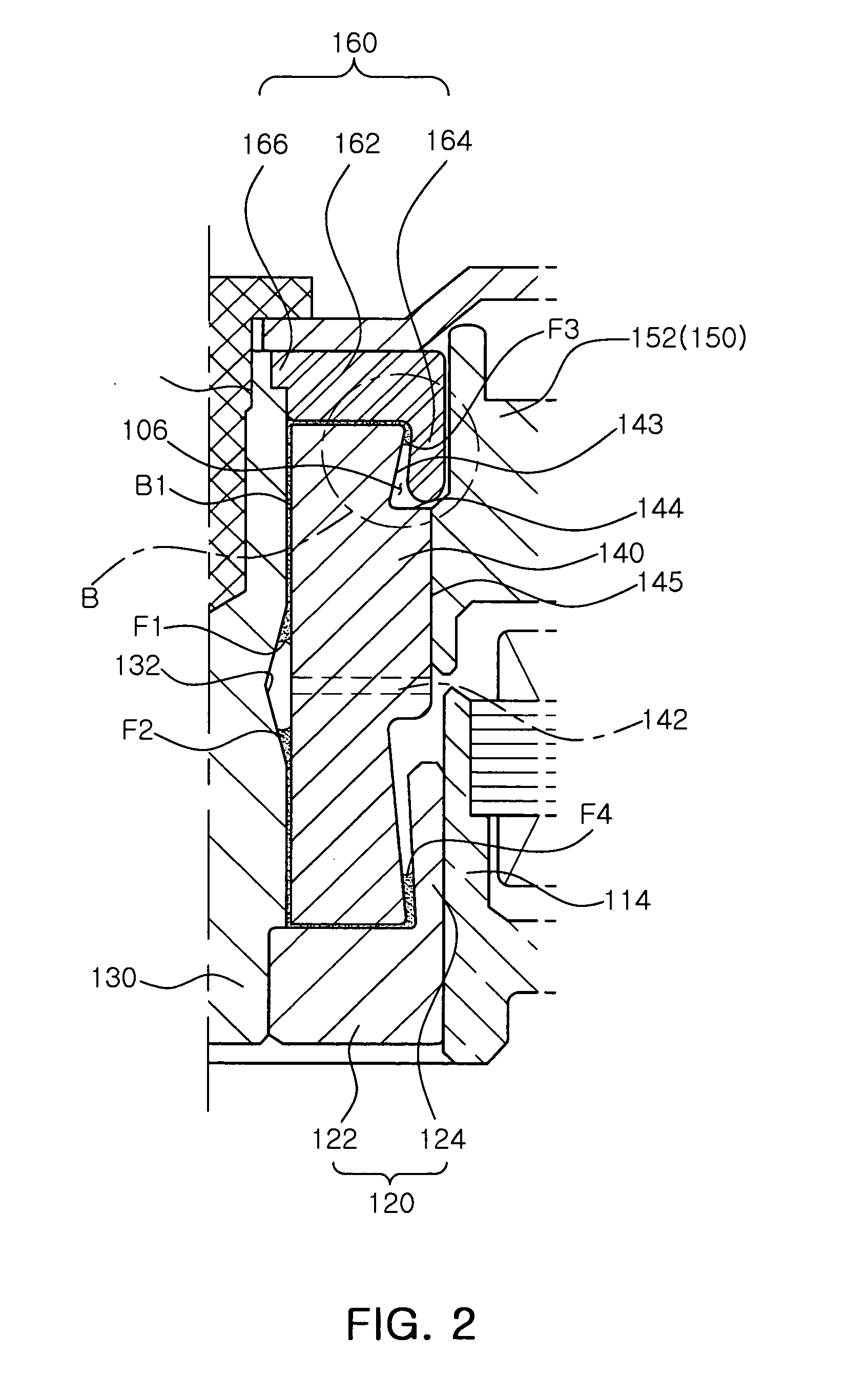
[0029]FIG. 1 is a cross-sectional view schematically showing a spindle motor according to an embodiment of the present invention. FIG. 2 is an enlarged view of part A of FIG. 1. FIG. 3 is a partial...


PUM


Abstract

A spindle motor including: a lower thrust member fixedly coupled to a base member; a shaft fixedly coupled to at least one of the lower thrust member and the base member; a sleeve disposed on an upper portion of the lower thrust member and rotatably installed on the shaft; a rotor hub coupled to the sleeve to thereby rotate together with the sleeve; an upper thrust member fixedly coupled to an upper end portion of the shaft and forming a liquid-vapor interface together with the sleeve; and a cover member fixedly coupled to the shaft so as to be disposed on an upper portion of the upper thrust member, wherein the upper thrust member includes a stepped jaw part having a lower surface supported by an upper surface of the shaft and an upper surface pressed by the cover member, so as to increase coupling strength with the shaft.

Description

CROSS-REFERENCE TO RELATED APPLICATIONS[0001]This application claims the priority of Korean Patent Application No. 10-2011-0077009 filed on Aug. 2, 2011, in the Korean Intellectual Property Office, the disclosure of which is incorporated herein by reference.BACKGROUND OF THE INVENTION[0002]1. Field of the Invention[0003]The present invention relates to a spindle motor, and more particularly, to a fixed shaft type spindle motor.[0004]2. Description of the Related Art[0005]A fixed shaft type spindle motor, in which a shaft having strong impact resistance is fixed to a case of a hard disk driving device, is generally mounted in an information recording and reproducing device such as a hard disk driving device for a server, or the like.[0006]That is, the shaft is fixedly installed in the spindle motor mounted in the hard disk driving device for a server in order to prevent information stored in the server from being damaged and or being unrecordable / unreadable due to an external impact....

Claims


Application Information

Patent Timeline
Patent Type & Authority Applications(United States)
IPC IPC(8): H02K7/08F16C32/06
CPCH02K1/28H02K7/085F16C17/107F16C33/745F16C2380/26F16C2370/12G11B19/20
Inventor YU, CHANG JO
Owner SAMSUNG ELECTRO MECHANICS CO LTD
Learn More