Light source apparatus

a light source and apparatus technology, applied in the direction of identification means, lighting support devices, with built-in power, etc., can solve the problems of lcd poor heat dissipation efficiency of lcd packaged with the conventional wire bonding process, and easy accumulation of lcd and other problems, to achieve the effect of good heat dissipation efficiency and better appearan

Inactive Publication Date: 2013-02-07
EVERGREEN OPTRONICS
View PDF8 Cites 31 Cited by
  • Summary
  • Abstract
  • Description
  • Claims
  • Application Information

AI Technical Summary

Benefits of technology

[0007]Accordingly, the invention is directed to a light source apparatus, which has good heat-dissipating efficiency and better appearance.
[0009]In the light source apparatus of the embodiment of the invention, since the LED chips are disposed in flip chip bonding way on the outer surface of the hollow rod-shaped base, so that the light source apparatus has both better appearance and good heat-dissipating efficiency. In addition, in the light source apparatus of the embodiment of the invention, since the LED chips are disposed surrounding the space formed by the hollow rod-shaped base, the appearance and the application level of the light source apparatus are effectively advanced.

Problems solved by technology

In general speaking, an LCD packaged with the conventional wire bonding process has a poor heat-dissipating efficiency and the produced heat is hard to be delivered onto the substrate bonded with the LCD and easily accumulated up.
However, the heat-dissipating fins often limit the shape modification of an LCD lamp, so that the lamp appears not have nice look.
In addition, a wire bonding way usually makes the thickness of an LED package too thick, which limits the appearance and application of the LED lamp.

Method used


Image

  • Light source apparatus
  • Light source apparatus
  • Light source apparatus

Examples


Embodiment Construction

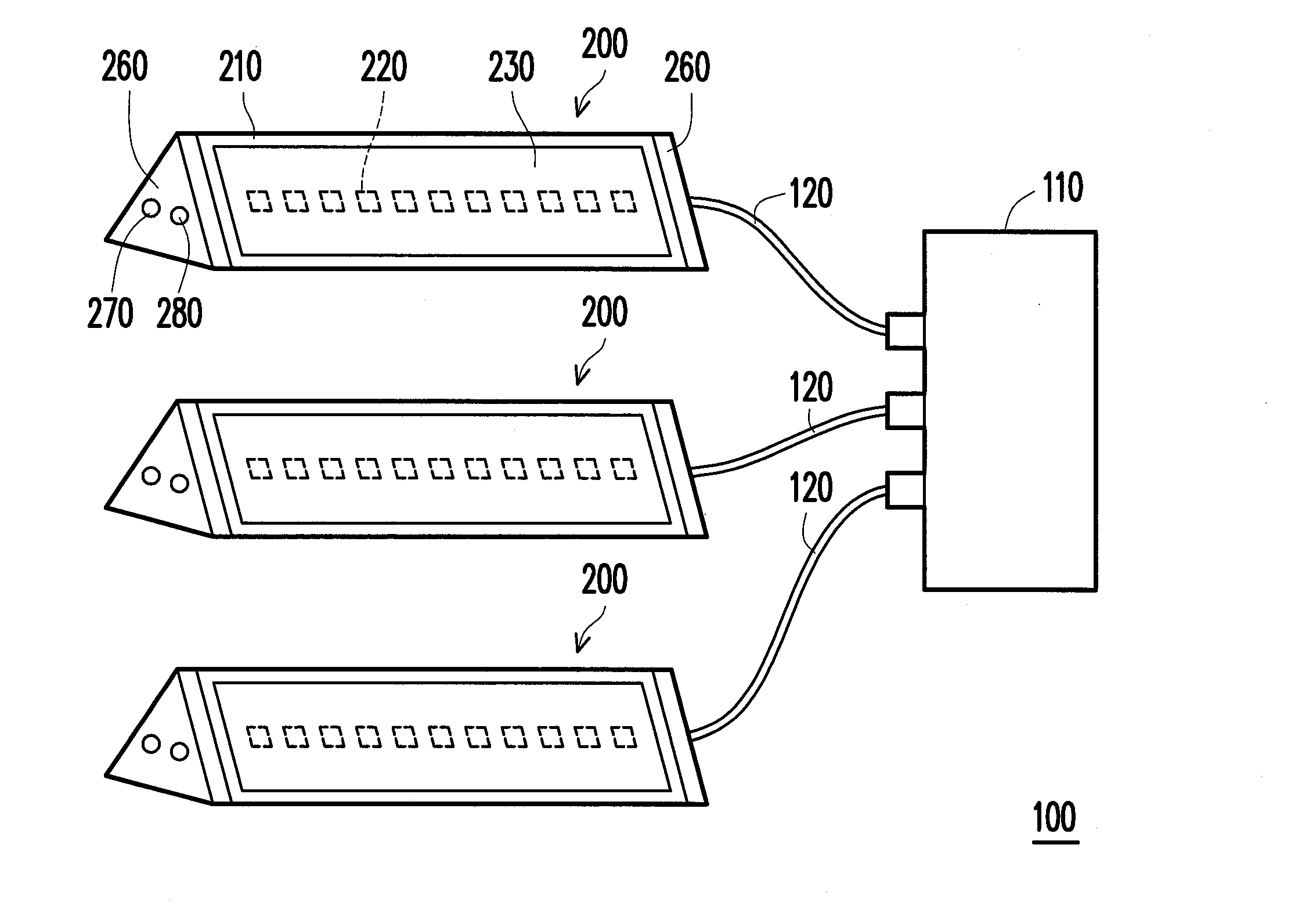
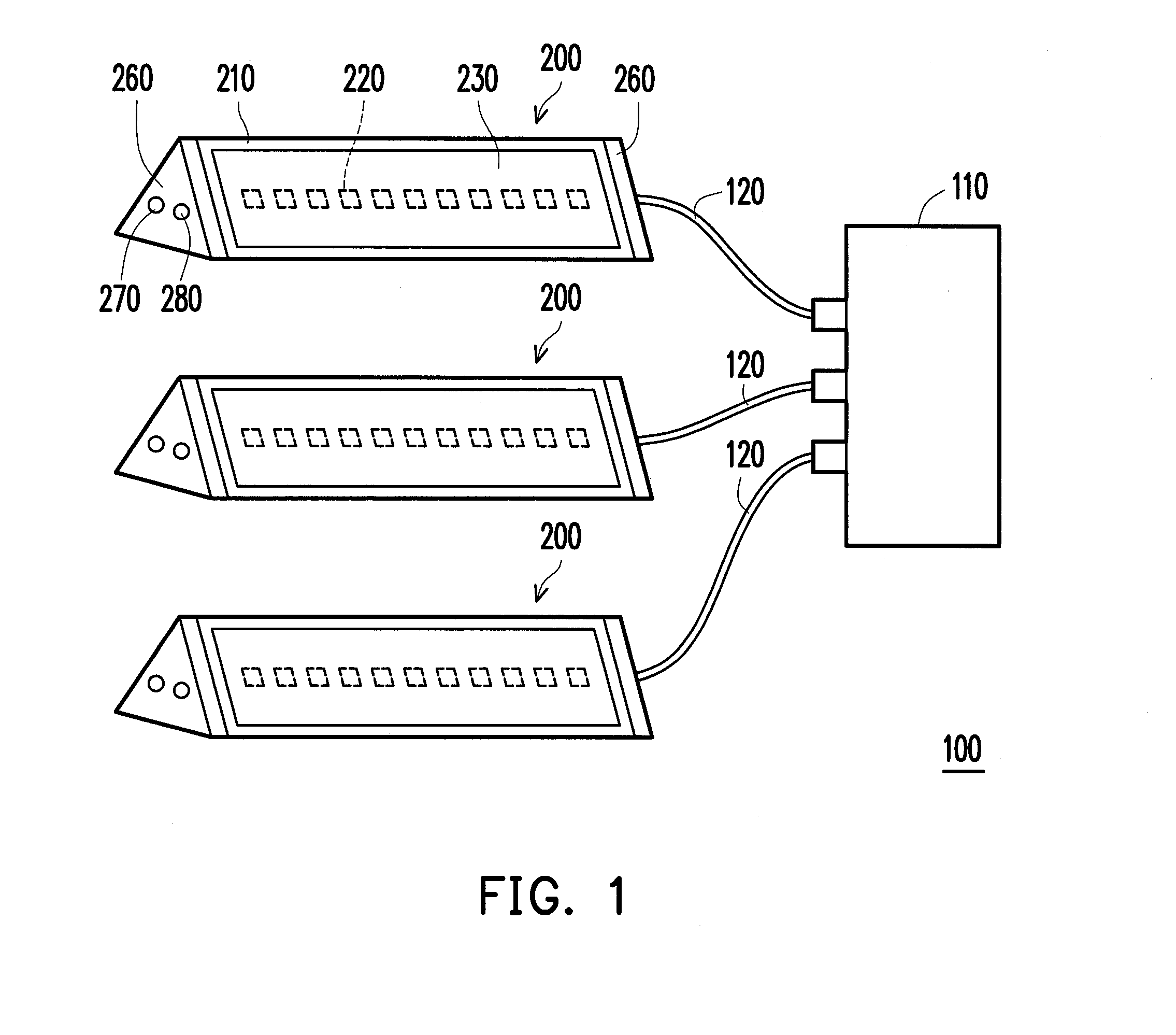
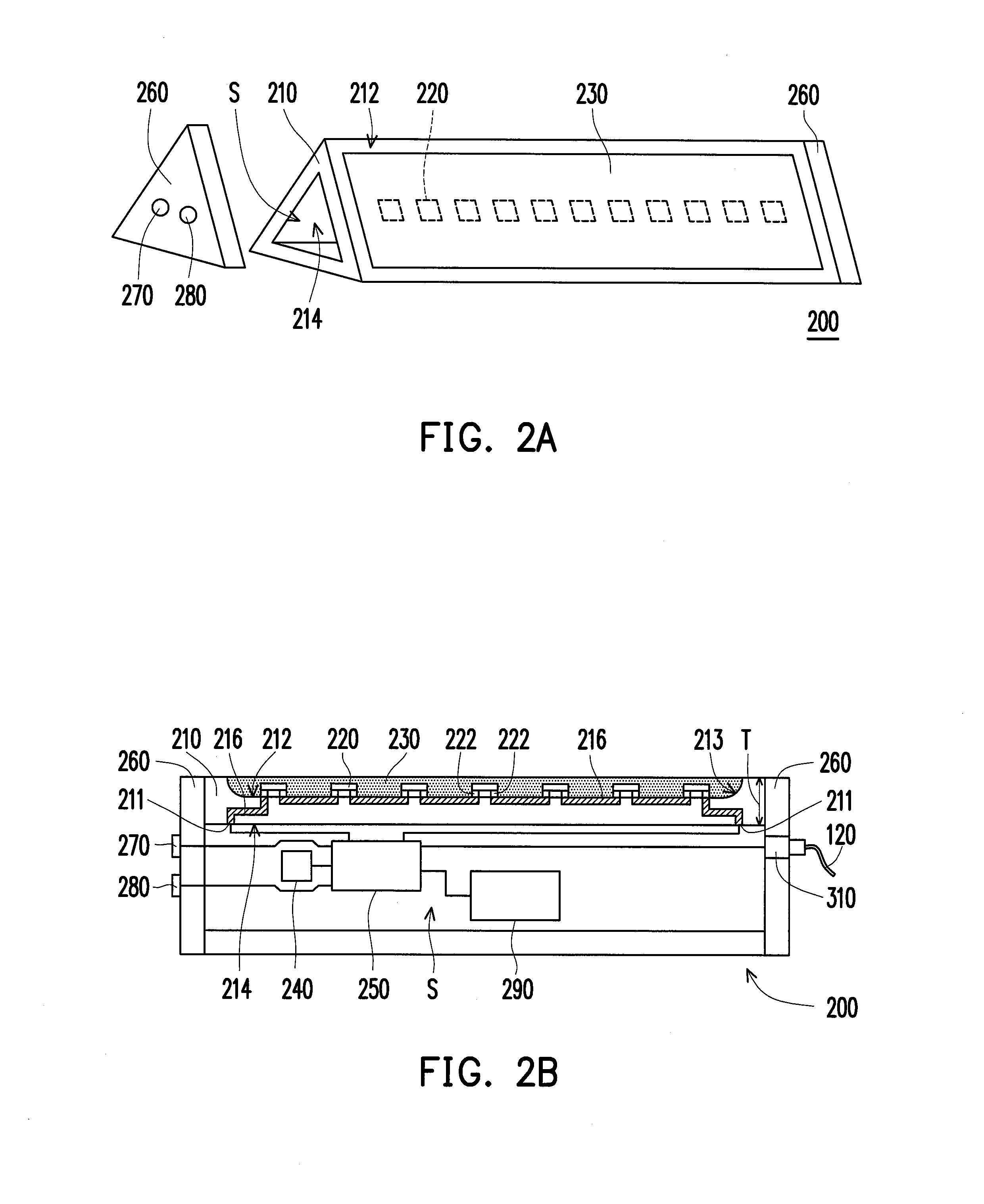
[0018]FIG. 1 is a schematic diagram of a light source apparatus according to an embodiment of the invention, FIG. 2A is a three-dimensional diagram of one of the light-emitting modules in FIG. 1, and FIG. 2B is a cross-sectional diagram of the light-emitting module in FIG. 1. For better understanding, in FIG. 2A, a cap is taken away from the hollow rod-shaped base of the light-emitting module. Referring to FIGS. 1, 2A and 2B, a light source apparatus 100 of the embodiment includes at least one light-emitting module 200 (a plurality of light-emitting modules 200 is shown in FIG. 1 as an example). Each of the light-emitting modules 200 includes a hollow rod-shaped base 210 and a plurality of LED chips 220. The hollow rod-shaped base 210 has an outer surface 212 and an inner surface 214 opposite to the outer surface 212, in which the inner surface 214 surrounds a space S. The LED chips 220 are disposed in flip chip bonding way on the outer surface 212 of the hollow rod-shaped base 210,...


PUM


Abstract

A light source apparatus includes at least a light-emitting module. The light-emitting module includes a hollow rod-shaped base and a plurality of LED chips. The hollow rod-shaped base has an outer surface and an inner surface opposite to the outer surface, in which the inner surface surrounds a space. The LED chips are disposed in flip chip bonding way on the outer surface of the hollow rod-shaped base, in which the LED chips are disposed surrounding the space.

Description

CROSS-REFERENCE TO RELATED APPLICATION[0001]This application claims the priority benefit of Taiwan application serial no. 100214541, filed on Aug. 5, 2011. The entirety of the above-mentioned patent application is hereby incorporated by reference herein and made a part of this specification.BACKGROUND[0002]1. Field of the Utility Model[0003]The invention generally relates to a light source apparatus, and particularly, to a light source apparatus with light emitting diode chips (LED chips).[0004]2. Description of Related Art[0005]Along with the progress of modern semiconductor science and technology, LEDs have been broadly used to provide electronic apparatuses such as traffic sign light, mega-size display board, scanner and LCD display with required light sources. The LED has advantages of fast response (10−9 seconds or so), small size, power-saving, low pollution (no mercury contained), high reliability and adaptation for mass production, it has been broadly applied as an indicator...

Claims


Application Information

Patent Timeline
Patent Type & Authority Applications(United States)
IPC IPC(8): H05B37/02F21L4/00F21L4/08F21V21/002
CPCF21Y2105/001F21V29/89F21S9/032F21V31/04F21L4/08F21S2/005F21S4/008F21S9/02F21V15/01F21V15/013F21V15/015F21V23/006F21V23/04F21V23/0435G09F9/33G09F13/22H05B33/0806H05B37/0245F21Y2101/02F21L2/00F21S2/00F21V29/70F21Y2111/005F21S4/28F21Y2105/10F21Y2107/30F21Y2115/10F21V9/30H05B45/30H05B45/357H05B47/175
Inventor LIAO, CHAO-JUNG
Owner EVERGREEN OPTRONICS
Why Eureka
Try Eureka