Method of depth-based imaging using an automatic trilateral filter for 3D stereo imagers

a technology of trilateral filter and depth-based imaging, applied in image enhancement, image analysis, instruments, etc., can solve the problems of small lens aperture, inability to achieve shallow depth of field, and inability to achieve the same artistic defocus effect that may be achieved with professional dslr cameras

Active Publication Date: 2013-02-07
SEMICON COMPONENTS IND LLC
View PDF4 Cites 70 Cited by
  • Summary
  • Abstract
  • Description
  • Claims
  • Application Information

AI Technical Summary

Problems solved by technology

Less expensive cameras (such as cellphone cameras and small point and shoot cameras) typically have small lens apertures that cannot achieve a

Method used


Image

  • Method of depth-based imaging using an automatic trilateral filter for 3D stereo imagers
  • Method of depth-based imaging using an automatic trilateral filter for 3D stereo imagers
  • Method of depth-based imaging using an automatic trilateral filter for 3D stereo imagers

Examples


Embodiment Construction

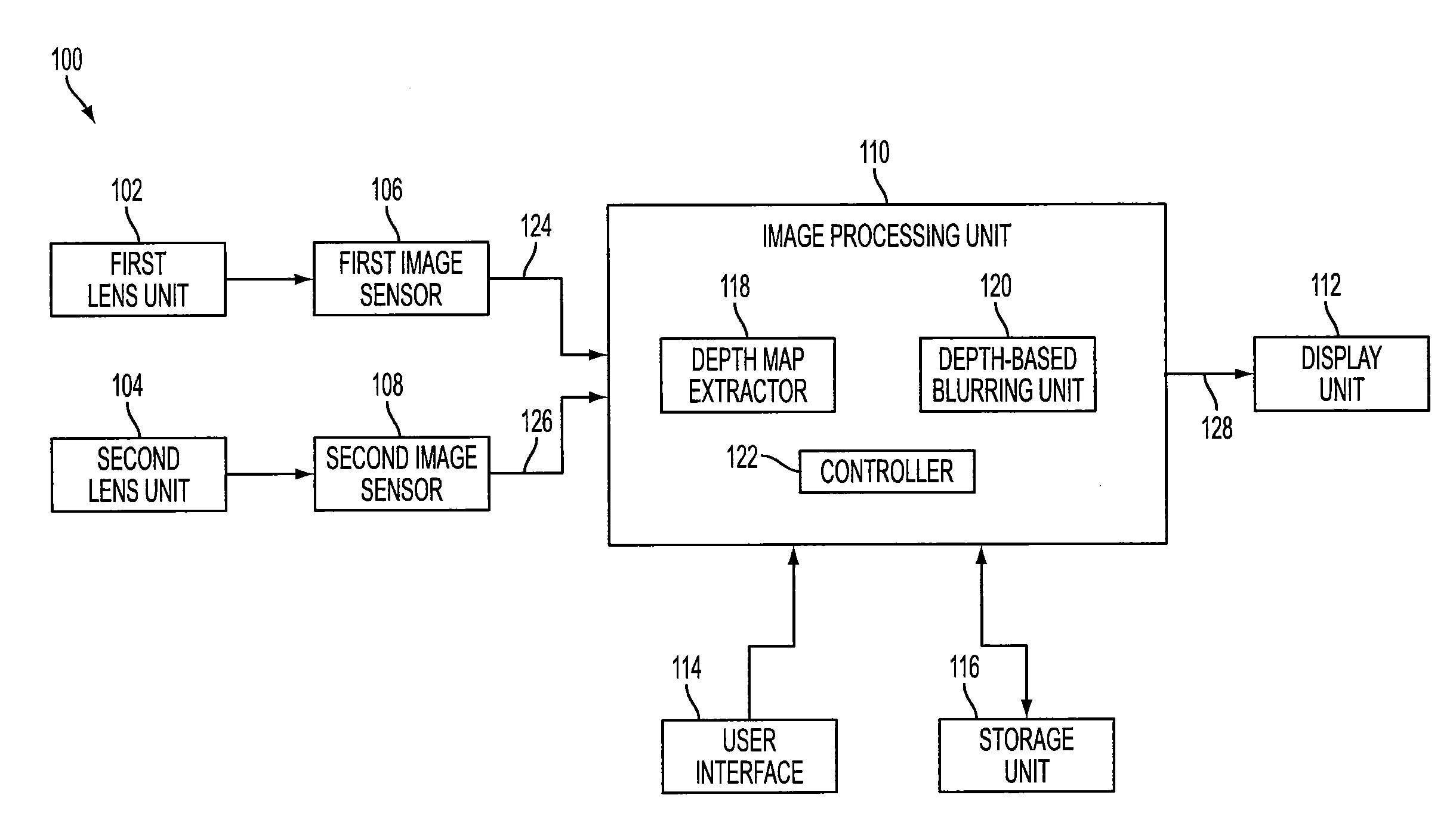
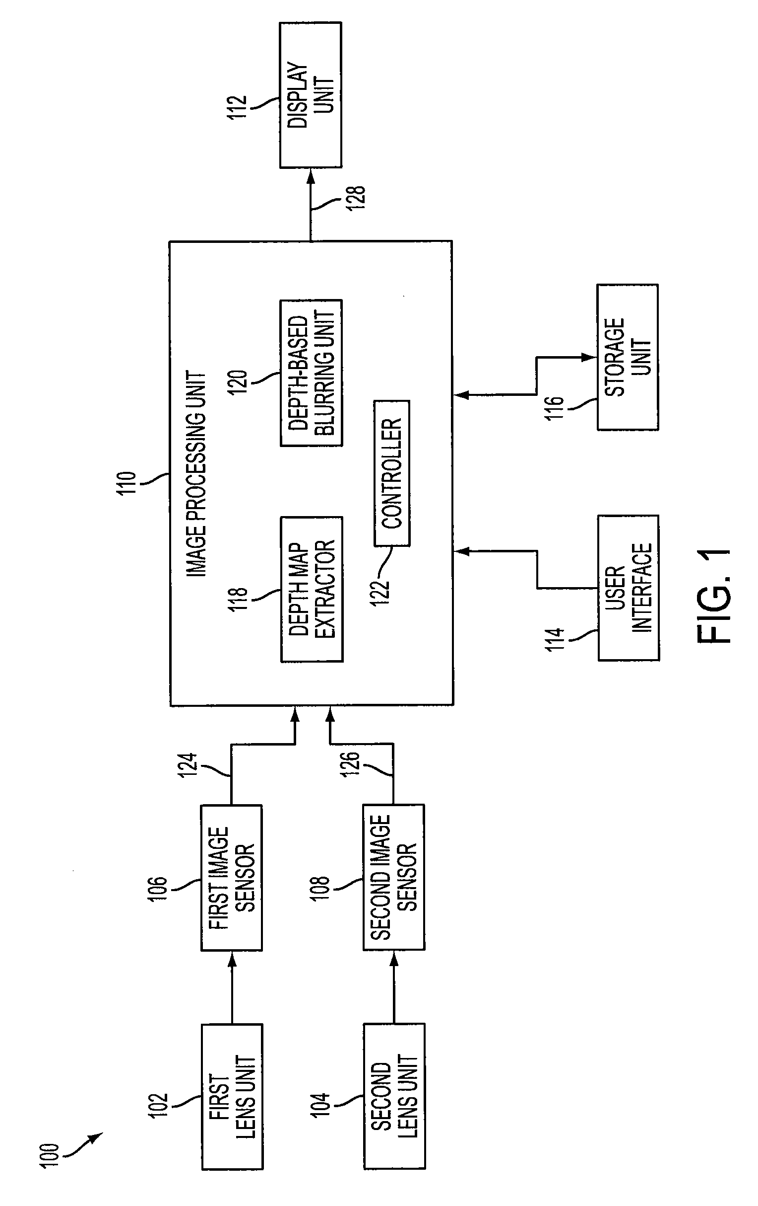
[0018]FIG. 1 is a block diagram of an example stereo imager, designated generally as 100. Stereo imager 100 includes first and second lens units 102, 104, first and second image sensors (or left and right image sensors) 106, 108, image processing unit 110 and display unit 112. Stereo imager 100 may also include user interface 114 and storage unit 116.

[0019]First and second lens units 102, 104 may gather light from an object and form images on respective regions of first image sensor 106 and second image sensor 108. As described further below with respect to FIG. 9, first and second image sensors 106, 108 may perform photoelectric conversion of light from respective first and second lens units 102, 104 into electric signals corresponding to first and second images 124, 126.

[0020]Image processing unit 110 may process the first and second images 124, 126 input from respective first and second image sensors 106, 108 to produce output image 128, which may be displayed on display unit 112...


PUM


Abstract

A system of stereo imagers, including image processing units and methods of blurring an image, is presented. The image is received from an image sensor. For each pixel of the image, a depth filter component is determined based on a focal area of the image and a depth map associated with the image. For each pixel of the image, a trilateral filter is generated that includes a spatial filter component, a range filter component and the depth filter component. The respective trilateral filter is applied to corresponding pixels of the image to blur the image outside of the focal area. A refocus area or position may be determined by imaging geometry or may be selected manually via a user interface.

Description

CROSS-REFERENCE TO RELATED APPLICATIONS[0001]This application claims priority of U.S. Provisional Patent Application Ser. No. 61 / 515,069, filed Aug. 4, 2011, which is incorporated herein by reference.FIELD OF THE INVENTION[0002]The present invention relates to depth-based imaging and, more particularly, to trilateral filters including a depth filter component to control the appearance of the depth of field.BACKGROUND OF THE INVENTION[0003]Shallow focus techniques are typically used by photographers to create images in which a portion of the scene is in focus and a remainder of the scene is out of focus. For example, shallow focus techniques may bring an object in the scene into sharp focus and the more distant background out of focus. This is sometimes referred to as the bokeh effect.[0004]To create the bokeh effect, a main object to be highlighted is positioned within the depth of field while the background is positioned out of the depth of field. The depth of field depends on a nu...

Claims


Application Information

Patent Timeline
IPC IPC(8): H04N13/02G06T5/00H04N13/122
CPCH04N13/0018H04N13/0239H04N13/0271G06T5/002G06T2207/20028G06T2200/04G06T2200/21G06T2207/10012G06T2207/10028G06T5/20H04N13/122H04N13/271H04N13/239
Inventor SUN, YAJIEPOPE, DAVID R.JIN, ELAINE WENYING
Owner SEMICON COMPONENTS IND LLC
Why Eureka
Try Eureka