Power supply unit using housing in which printed circuit board is housed

Active Publication Date: 2013-02-07
DENSO CORP
View PDF5 Cites 78 Cited by
  • Summary
  • Abstract
  • Description
  • Claims
  • Application Information

AI Technical Summary

Benefits of technology

[0030]Further, preferably, the cooling member is formed along one short side of the housing, including the corners sandwiching the short side. This location of the cooling member increases the degree of freedom in the design, height and density of

Problems solved by technology

Accordingly, it is difficult to ensure a space for mounting the circuit elements for the control circuit board on the upper surface of the base plate.
However, an attempt of reducing the size of the housing raises a problem that the circuit elements or parts arranged in the gap

Method used


Image

  • Power supply unit using  housing in which printed circuit board is housed
  • Power supply unit using  housing in which printed circuit board is housed
  • Power supply unit using  housing in which printed circuit board is housed

Examples


first embodiment

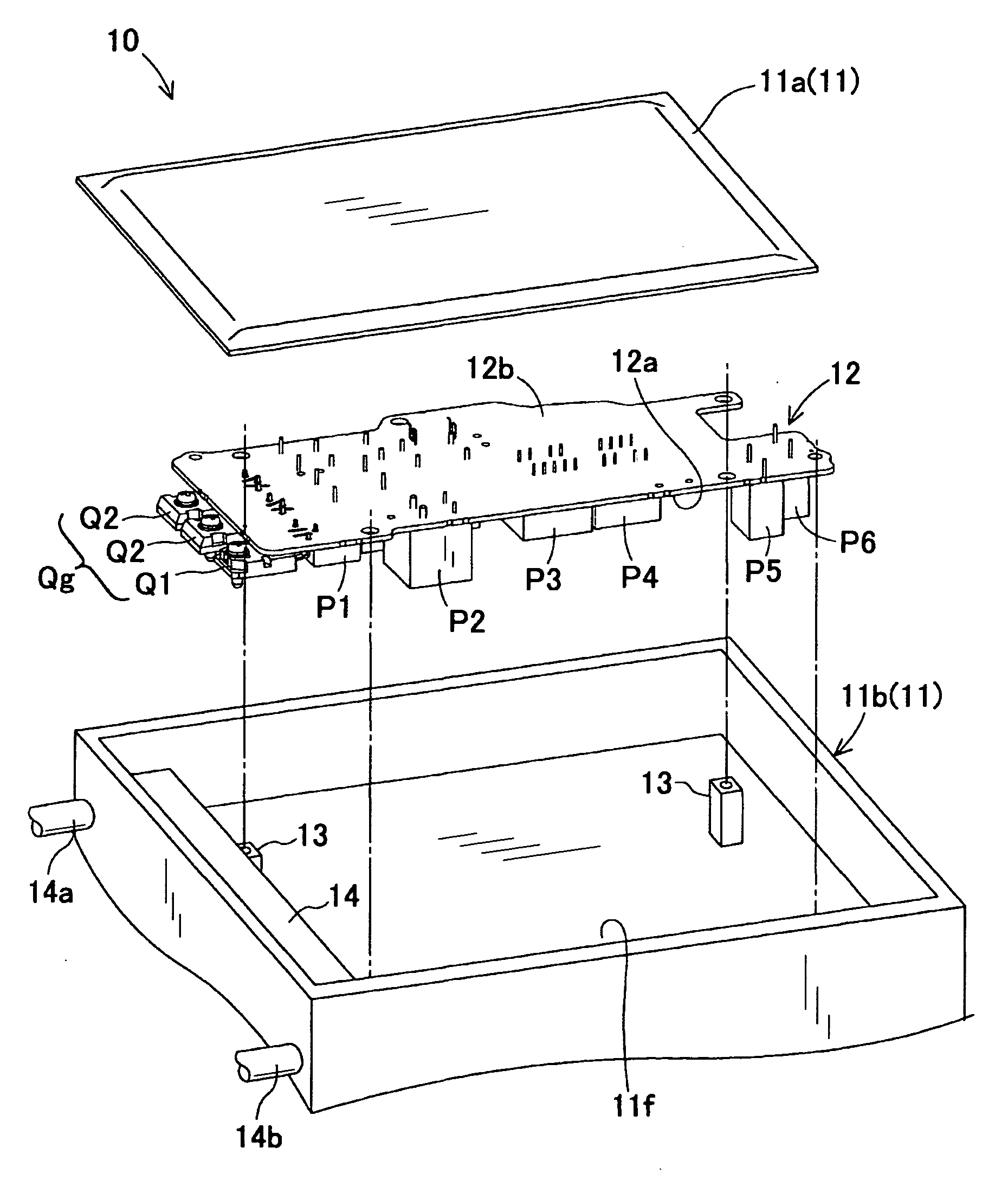
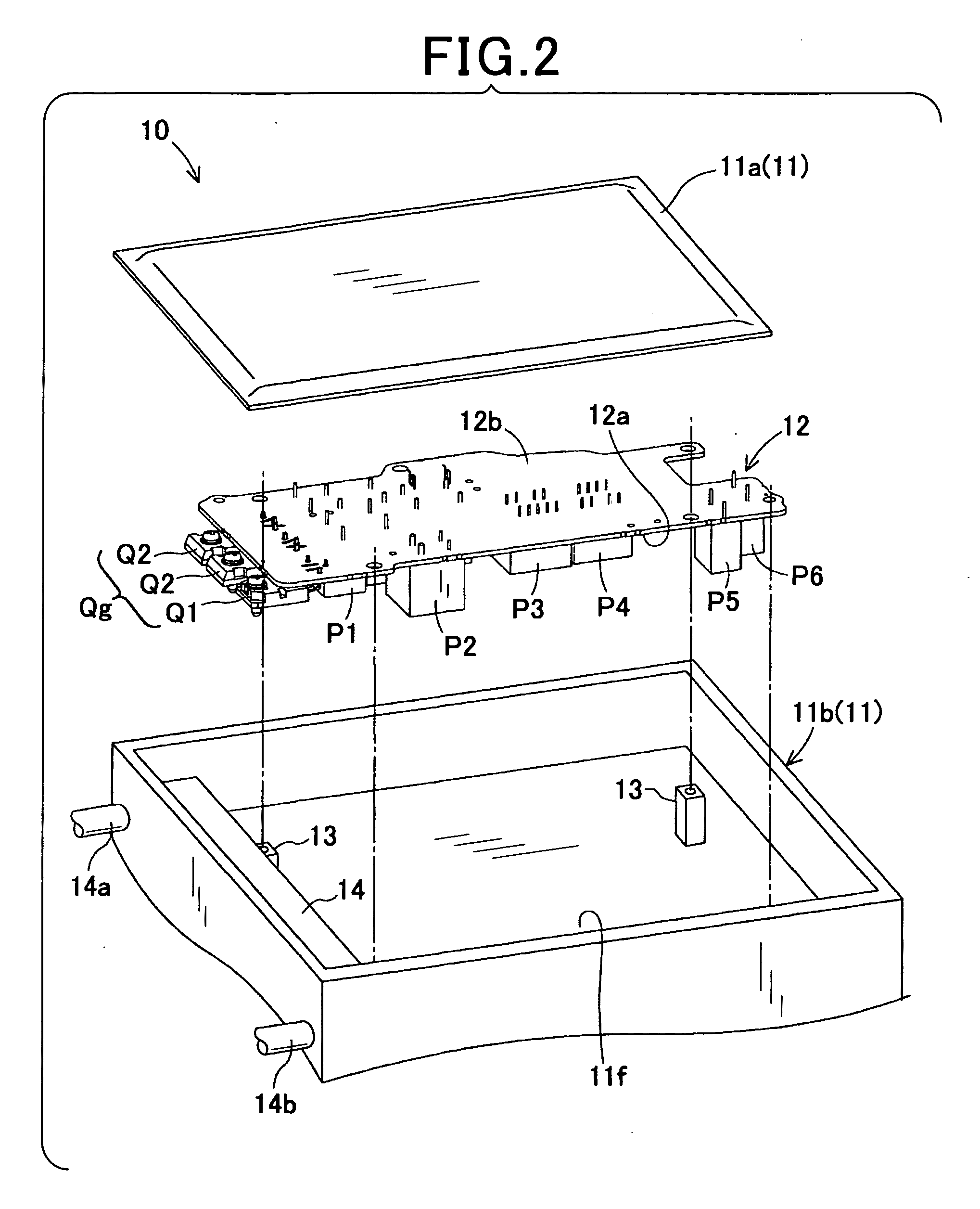
[0043]Referring to FIGS. 2 to 5, a first embodiment of the present invention is described. FIG. 2 is an exploded schematic perspective view of a power supply unit 10.

[0044]The power supply unit 10 shown in FIG. 2 is a so-called DC-DC converter. The power supply unit 10 has a function of converting DC voltage supplied from a power source (e.g., a battery or a fuel cell) into desired voltage and of outputting the converted voltage. The power supply unit 10 includes a housing 11, a printed circuit board 12 and accommodation components, not shown. The term of accommodation components refers to parts and the like accommodated inside the housing 11, i.e. parts and the like that are not arranged on the printed circuit board 12. For example, the accommodation components include circuit elements (e.g., a rectifier circuit, a transformer and a filter circuit), an insert bus bar (see FIG. 7 and FIGS. 8A to 8C) described later, and the like.

[0045]The housing 11 is composed of a housing cover 11...

second embodiment

[0064]Referring now to FIG. 6, a second embodiment that is a modification of the first embodiment is described. It should be appreciated that, in the second and the subsequent embodiments, the components identical with or similar to those in the first embodiment are given the same reference numerals for the sake of omitting unnecessary explanation.

[0065]FIG. 6 is a cross-sectional view illustrating the power supply unit 10 of the second embodiment, taken along a line V-V of FIG. 3. The second embodiment is described focusing on the differences from the first embodiment.

[0066]The second embodiment shown in FIG. 6 is different from the first embodiment in that the housing body 11b in the second embodiment is provided with a projection 18 which is projected from the bottom surface 11f toward the front mounting surface 12a. The projection 18 having a shape of a seat has a height which is of a level that an end surface thereof comes into contact with or close to a different-shape compone...

third embodiment

[0071]Referring to FIG. 7 and FIGS. 8A to 8C, hereinafter is described a third embodiment of the present invention which is a modification of the first and second embodiments described above. FIG. 7 is a cross-sectional view illustrating the power supply unit 10 of the third embodiment, taken along a line V-V of FIG. 3. FIGS. 8A to 8C illustrate an insert bus bar 19 according to the third embodiment. The third embodiment is described focusing on the differences from the first and second embodiments.

[0072]The third embodiment shown in FIG. 6 is different from the second embodiment shown in FIG. 6 in that, in the third embodiment, the insert bus bar 19 is partially or entirely inserted into a gap formed between the different-shape components group Pg arranged on the front mounting surface 12a and the bottom surface 11f. The insert bus bar 19 includes terminals, a terminal block, wiring and the like and has a function of electrically connecting the circuit components with each other. I...


PUM


Abstract

In a power supply unit, a printed circuit board is provided on which two or more different-shape components are mounted. Such components include semiconductor devices. The printed circuit board has a designated mounting surface of the board. The housing is also provided, which houses the printed circuit board and comprises a cooling member for cooling a first space formed between the mounting surface and an opposed surface in the housing. The opposed surface is opposed to the mounting surface. The cooling member is arranged at part of the opposed surface, the part of the opposed surface projects toward the semiconductor devices, and the opposed surface is opposed to the two or more types of different-shape components.

Description

CROSS-REFERENCE TO RELATED APPLICATION[0001]This application is based on and claims the benefit of priority from earlier Japanese Patent Application No. 2011-167966 filed Aug. 1, 2011, the description of which is incorporated herein by reference.BACKGROUND[0002]1. Technical Field[0003]The present invention relates to a power supply unit using a printed circuit board accommodated in a housing which is provided with a cooling member.[0004]2. Related Art[0005]Switching power supply units are well known. For example, JP-A-2002-345245 discloses an example of a technique related to a switching power supply unit. This switching power supply unit is able to increase packaging density of components, easily reduce size, reduce resistance loss at terminal connecting portions and enhance power supply efficiency. Also, in this switching power supply unit, a transformer, lead portions, electrode members and the like are fixed to one designated surface of a given circuit board. The lead portions, ...

Claims


Application Information

Patent Timeline
IPC IPC(8): H05K7/20H02M1/00
CPCH05K7/20927
Inventor HOSODA, TSUYOSHI
Owner DENSO CORP
Why Eureka
Try Eureka