System and method for managing multiple transmission resources of a spatial multi-cell radio-communication system

a radio-communication system and multi-cell technology, applied in the direction of radio transmission, electrical equipment, transmission, etc., can solve the problems of difficult to achieve communication with such a direct transposition architecture, and achieve the effect of reducing the size of the cell and being flexible and efficien

Inactive Publication Date: 2013-02-07
CENT NAT DETUD SPATIALES C N E S
View PDF5 Cites 17 Cited by
  • Summary
  • Abstract
  • Description
  • Claims
  • Application Information

AI Technical Summary

Benefits of technology

[0015]An effort is being made to make the management of traffic switches and transmission resource changes more flexible and efficient in the satellite system so as to make the decreased size of the cells compatible with the misalignment speeds of the satellite antenna.

Problems solved by technology

Flexible and effective management in terms of capacity of the broadband transmission resources that simultaneously guarantees service continuity in terms of absence of interruption and communications appears difficult to achieve with such a directly transposed architecture.

Method used


Image

  • System and method for managing multiple transmission resources of a spatial multi-cell radio-communication system
  • System and method for managing multiple transmission resources of a spatial multi-cell radio-communication system
  • System and method for managing multiple transmission resources of a spatial multi-cell radio-communication system

Examples


second embodiment

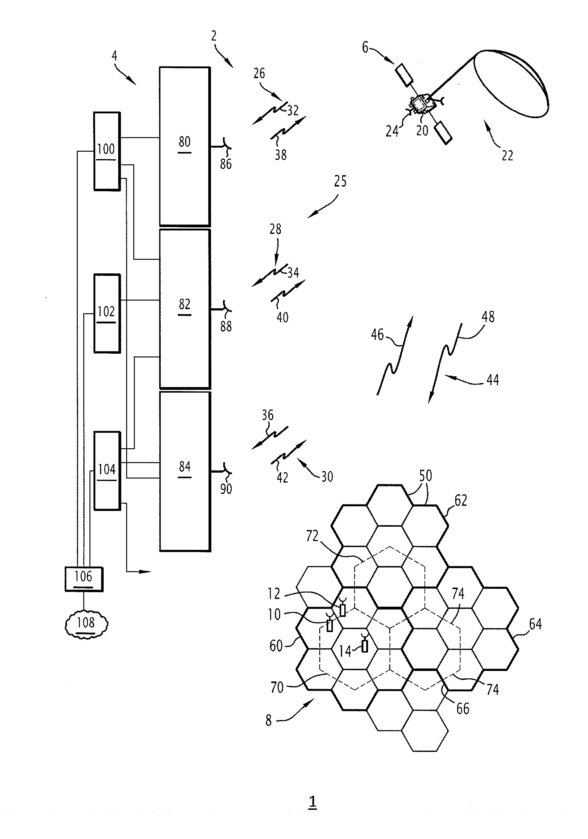
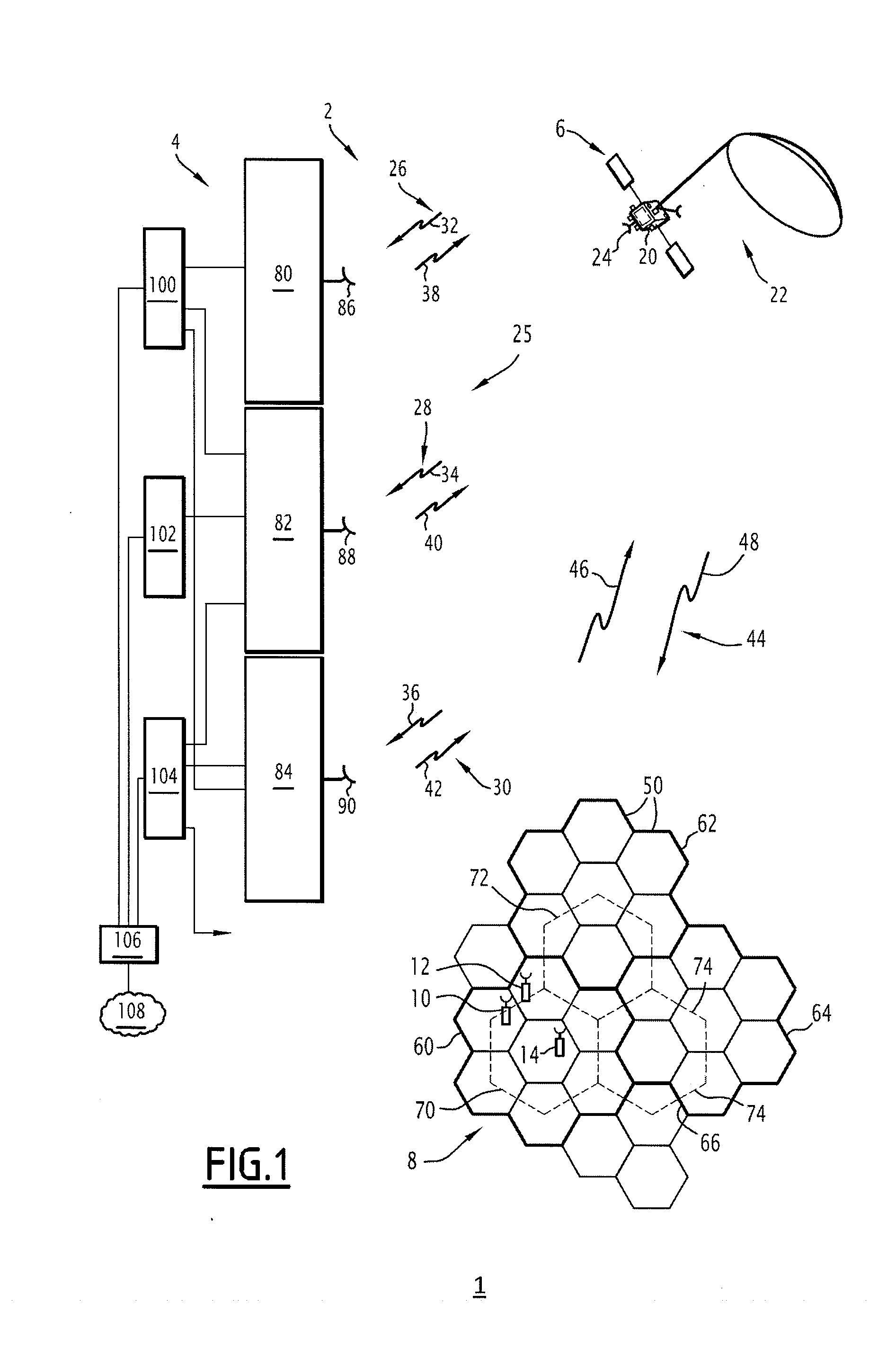
[0177]According to FIG. 6, the multi-cell radio communication system is shown, in which each virtual cell exploits all of the frequency bands of a different cluster of beams.

[0178]The three satellite access stations 80, 82, 84 illustrated are identical to those of FIGS. 1 and 3, and the distribution of the frequency bands in the beams of FIG. 1 is identical to that of FIG. 2.

[0179]Three coordinating stations 524, 526, 528, each associated with a different virtual cell are each respectively connected to a different satellite access station 80, 82, 84.

[0180]Here, each virtual cell is combined, in terms of beams, with all of the coverage of the cluster with which it is associated.

[0181]Each frequency band transposition of a same satellite access station is connected to the control station associated with the access station.

[0182]For example, each transposition unit 124, 126, 128, 129, 130, 132, 134 of the first access station 82 is connected to the first control unit 526 through respec...

first embodiment

[0183]It is assumed here, as in the first embodiment, that each band B(k) is subdivided into three sub-bands SB(k, j), j varying from 1 to 3, and each transposition unit comprises three sub-band transposition units not shown in FIG. 6.

[0184]The first virtual cell control unit 526 is configured to manage communications in which the assigned transmission channels use at least two sub-bands as transmission resources, two of them each belonging to a different frequency band.

[0185]For example, the control unit 526 can process the sub-band SB(1, 2) and the sub-band SB(7, 2) assigned to the first cluster as resources for a same transmission channel.

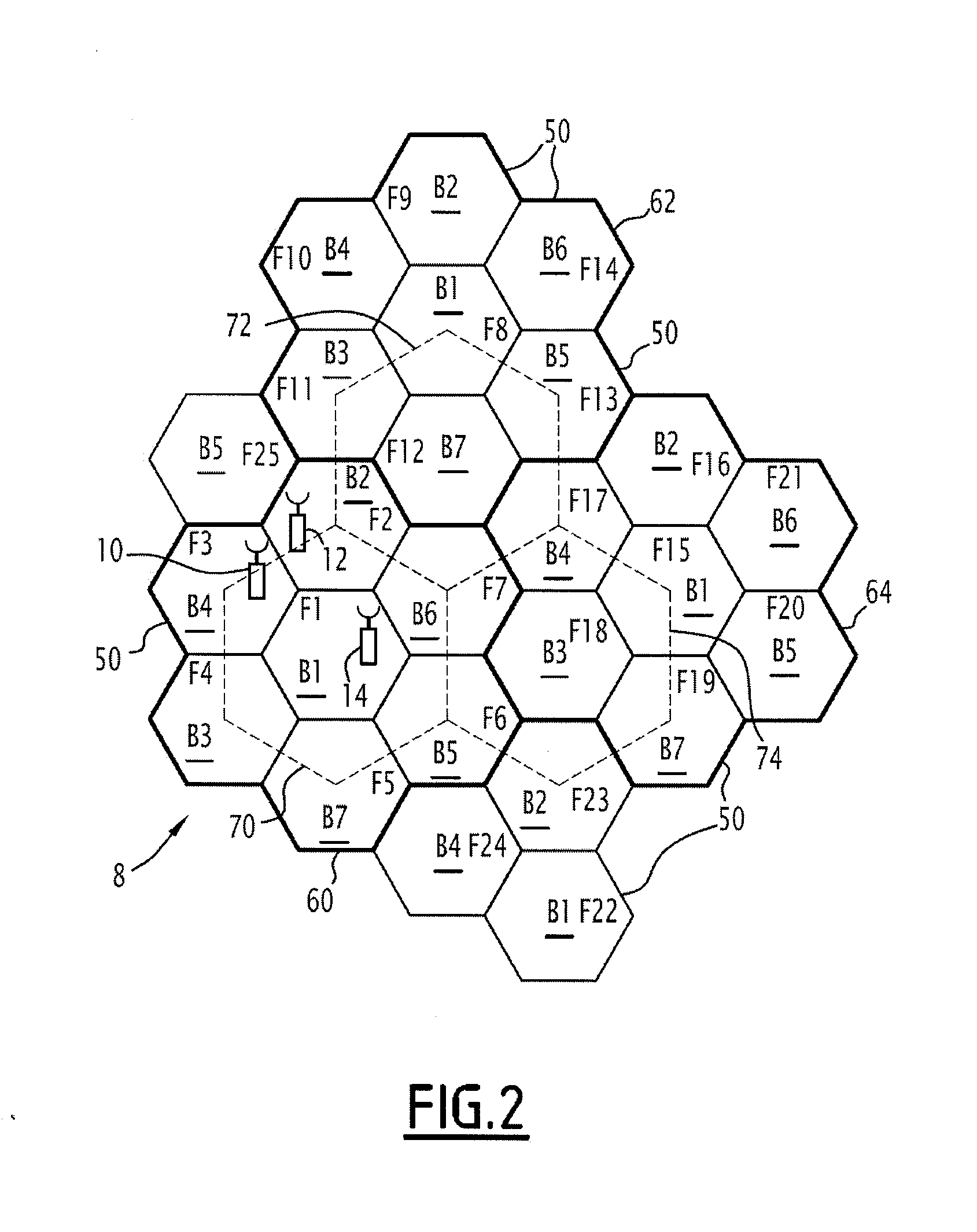
[0186]FIG. 7 illustrates a coverage alternative 600 of beams 602 and frequency band distribution in the beams.

[0187]Here, 25 beams are shown and arranged in five rows of five beams having a square shape.

[0188]Allocated to the beams of the first row at the top of FIG. 7, from left to right, are respectively the frequency bands B3, B1, B4, B2, B5,...


PUM


Abstract

A satellite cellular radio-communication system using beam formation is provided. The system includes a satellite, at least one satellite access station, terminals, at least one control unit of a virtual cell. At least one of the terminals is configured to transmit and receive on a transmission channel having at least two frequency and spatial transmission resources of a same virtual cell that are different by their frequency band, a frequency and spatial transmission resource being a sub-band of a frequency band used in a beam. The frequency band is taken from among a predetermined number of frequency bands and was allocated to said beam according to a reuse function.

Description

[0001]This claims the benefit of French Patent Application FR 11 57151, filed Aug. 4, 2011 and hereby incorporated by reference herein.[0002]The present invention relates to a system for managing multiple transmission resources of a spatial multi-cell radio-communication system based upon at least one satellite and a method for managing transmission resources implemented by such a system.BACKGROUND[0003]Satellite-based multi-cell radio-communication satellite systems already exist, for example such as the THURAYA system.[0004]An ETSI standard, designated “GEO-Mobile Radio Interface Specifications; Part 3: Network Specifications; Sub-part 2: Network architecture; GMR-1 03.002,” also defines the architecture of the satellite component of a multi-cell system for narrow bandwidth services in the context of the UMTS (Universal Mobile Telecommunication System).[0005]Standards for new generation land-based systems called pre-fourth generation, or 3.9G, such as LTE (Long-Term Evolution 3GPP...

Claims


Application Information

Patent Timeline
Patent Type & Authority Applications(United States)
IPC IPC(8): H04W72/04H04W36/06
CPCH04B7/185H04W72/20H04B7/18528H04W72/0453
Inventor ROS, BENJAMINBOUSTIE, CHRISTELLESCOT, GAEL
Owner CENT NAT DETUD SPATIALES C N E S
Why Eureka
Try Eureka