Eureka AIR delivers breakthrough ideas for toughest innovation challenges, trusted by R&D personnel around the world.

Radiotherapy

Inactive Publication Date: 2013-02-07
ELEKTA AB
View PDF4 Cites 5 Cited by
  • Summary
  • Abstract
  • Description
  • Claims
  • Application Information

AI Technical Summary

Benefits of technology

The patent describes a new collimation apparatus for a radiation head used in IMRT treatments. The apparatus includes an adjustable block and a set of individually moveable leaves. By adjusting the position of the leaves on one bank of the MLC, the front of the collimator presents a straight, uniform front at all relevant times. This improves the quality of the radiation field. The block also has an adjustable section that can change the angle between the beam axis and the leading edge, reducing the penumbra and creating a better definition of the radiation field. Overall, this new design offers weight and height reductions relative to known radiation heads and avoids problems associated with interdigitation.

Problems solved by technology

That radiation is partially absorbed by the lesion, causing cell damage which inhibits growth of the lesion and / or causes it to reduce in size.
In particular, there is a small but finite amount of leakage of radiation through the very small gaps between the leaves.
However, there is usually still enough leakage for manufacturers to provide additional collimators in the form of so-called “block collimators”, substantial tungsten blocks similar in depth to the leaves, and extending across the entire width of the radiation aperture.

Method used


Image

  • Radiotherapy
  • Radiotherapy
  • Radiotherapy

Examples


Embodiment Construction

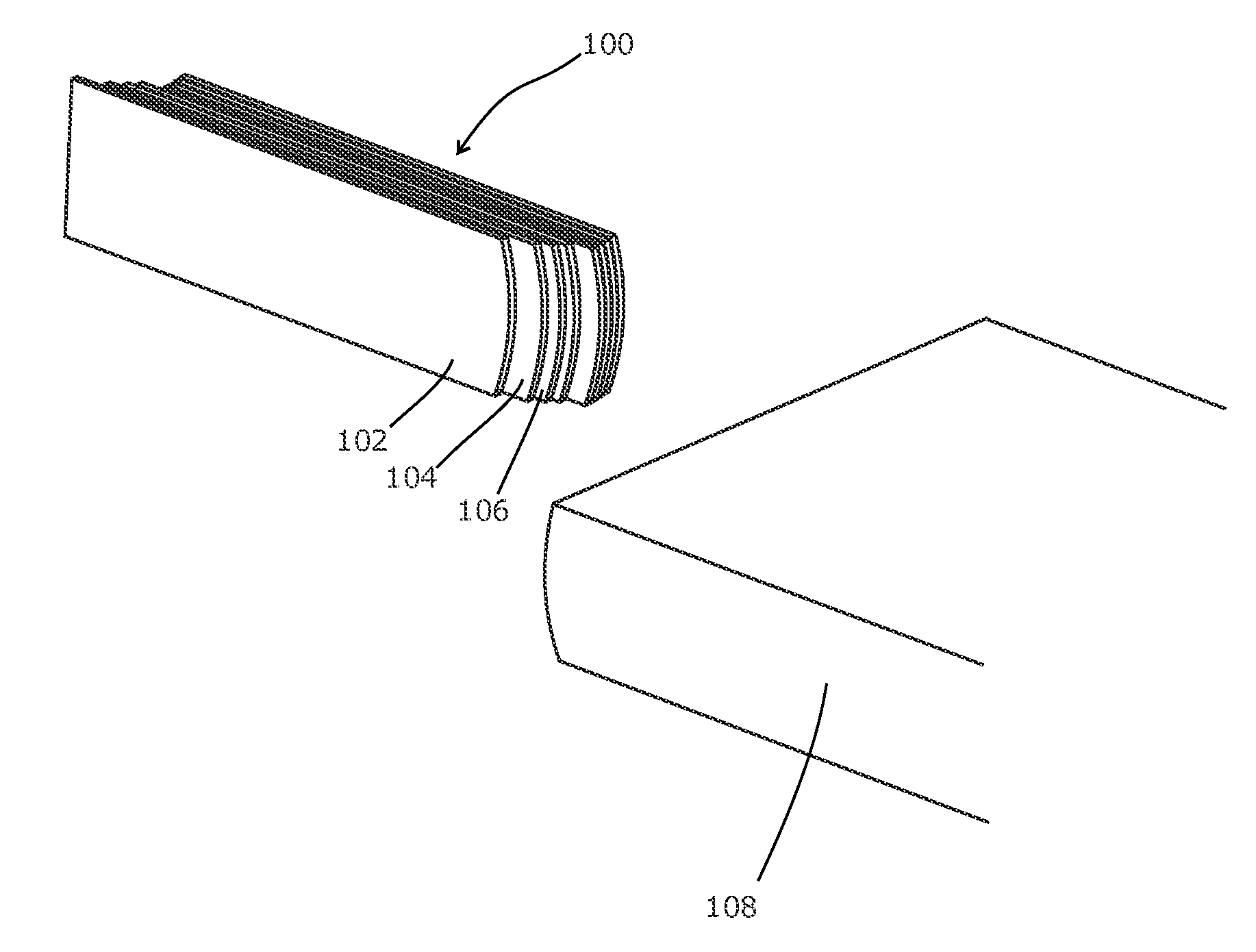
[0035]Referring to FIG. 6, the collimator set of the present invention for use in a radiotherapy apparatus comprising left and right collimators, each projecting into the beam from opposing sides of the apparatus. The left collimator 100 is a multi-leaf collimator as described above, and comprises a large number of leaves 102, 104, 106, some of which are illustrated and some of which are omitted for clarity. As discussed above, the left collimator may have 40, 80 or 160 leaves, or any other number.

[0036]The right collimator 108 is a single block collimator. Its cross-section in a plane parallel to the MLC leaves is substantially the same as the individual leaves, but it is in the form of a single block that extends across the entire width of the beam aperture.

[0037]FIG. 7 shows the collimator set, viewed along the beam. The left collimator 100 is able to define an arbitrary shape subject only to the usual limitations of an MLC leaf bank. The right collimator 108 can define a straigh...


PUM


Abstract

Radiotherapy apparatus is disclosed, comprising a radiation source capable of emitting a beam of therapeutic radiation along a beam axis, collimation apparatus for delimiting the beam and comprising (i) a block of sufficient width to extend across the width of the beam, selectively movable into the beam from a first side of the beam axis, and (ii) an array of individually moveable elongate narrow leaves arranged side-by-side in a direction perpendicular to the beam, each being moveable longitudinally into the beam from a second and opposing side of the beam axis, in which there is no array of individually moveable elongate narrow leaves arranged side-by-side in a direction perpendicular to the beam moveable longitudinally into the beam from the first side of the beam axis. Thus, there is in effect a single bank of MLC leaves on one side of the aperture and a block collimator on the other.

Description

[0001]This application is a continuation of Patent Cooperation Treaty Patent Application PCT / EP2011 / 002130, filed Apr. 28, 2011, which is incorporated herein by reference.FIELD OF THE INVENTION[0002]The present invention relates to improvements in the apparatus and related processes for the delivery of radiotherapy.BACKGROUND ART[0003]Radiotherapy consists of the treatment of tumours and other lesions by directing harmful radiation towards the site of the lesion. That radiation is partially absorbed by the lesion, causing cell damage which inhibits growth of the lesion and / or causes it to reduce in size.[0004]The radiation is also capable of causing harm to surrounding healthy tissue, albeit at a slightly lesser rate in the case of cancerous lesions. Whilst it is impossible to completely prevent the irradiation of healthy tissue, given that some tissue will be in front of or behind the lesion, the amount of healthy tissue that is irradiated is generally minimised by careful collimat...

Claims


Application Information

Patent Timeline
IPC IPC(8): A61N5/10
CPCA61N5/1045
Inventor CLAESSON, BENGT KE
Owner ELEKTA AB
Why Eureka
Eureka Blog
Learn More