Method for cooling a gas turbine plant and gas turbine plant for implementing the method

a gas turbine and gas turbine technology, applied in the field of gas turbines, can solve the problems of increasing the overall length and mixing losses

Inactive Publication Date: 2013-02-14
ANSALDO ENERGIA SWITZERLAND AG
View PDF4 Cites 51 Cited by
  • Summary
  • Abstract
  • Description
  • Claims
  • Application Information

AI Technical Summary

Problems solved by technology

The addition of cooling air leads to mixing losses in the compressor and

Method used


Image

  • Method for cooling a gas turbine plant and gas turbine plant for implementing the method
  • Method for cooling a gas turbine plant and gas turbine plant for implementing the method
  • Method for cooling a gas turbine plant and gas turbine plant for implementing the method

Examples


Embodiment Construction

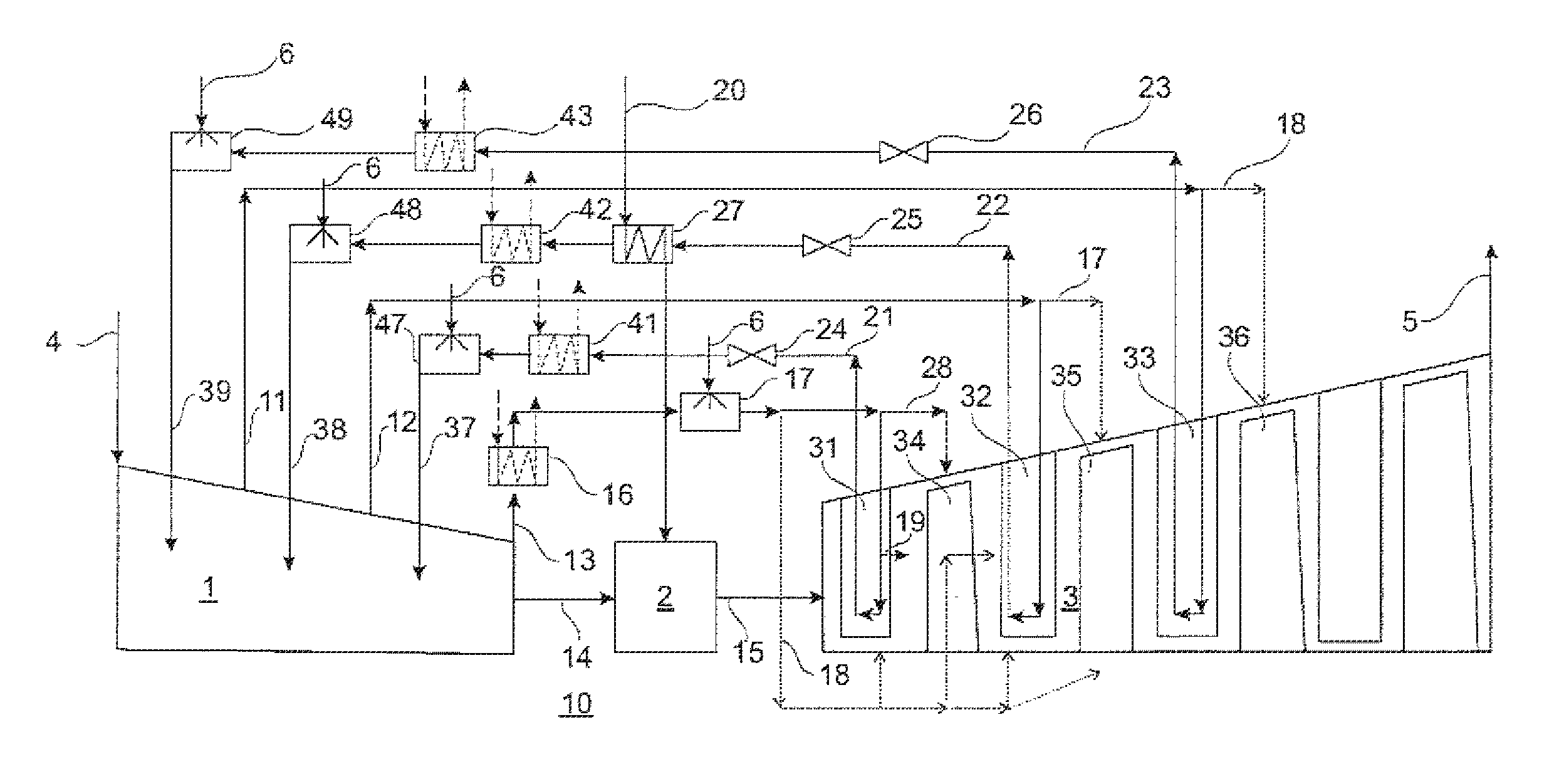
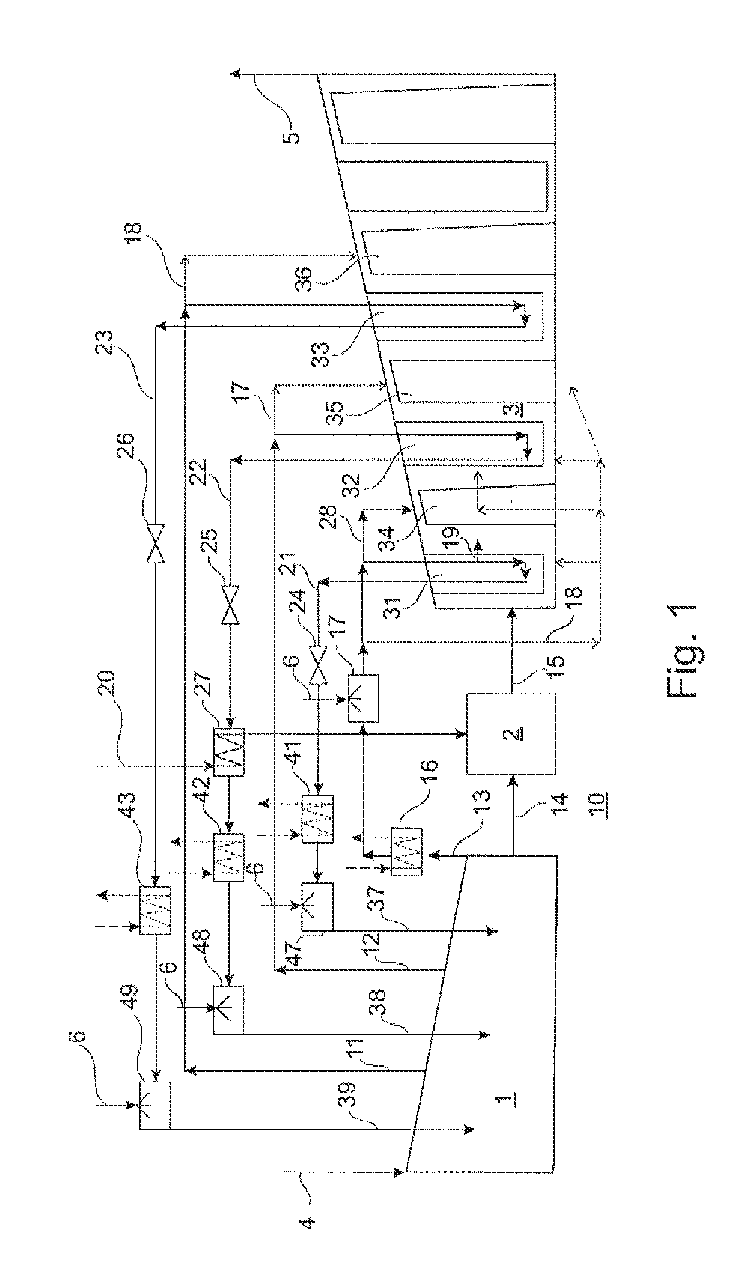
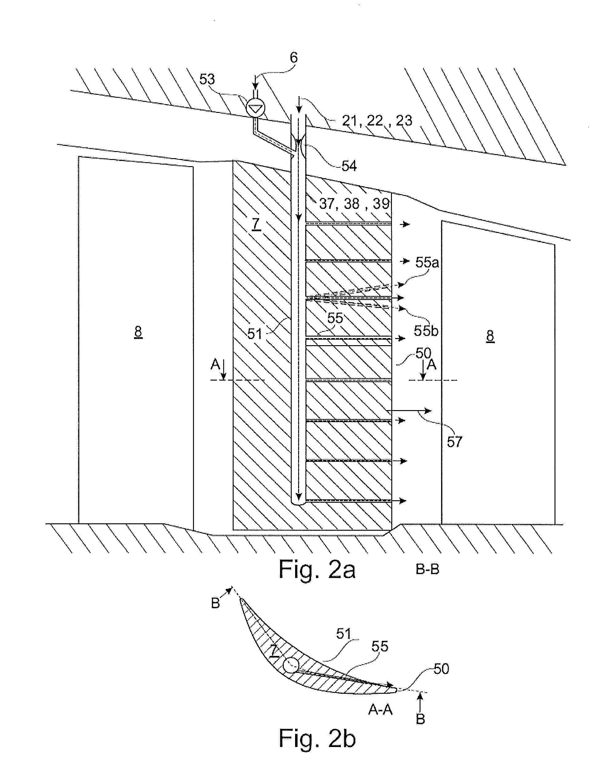
[0015]Exemplary embodiments of the present disclosure provide a cooling method for a gas turbine plant and also a gas turbine plant for implementing the method, which avoid the disadvantages of known methods or of gas turbine plants. The exemplary embodiments of the present disclosure, in contrast to known techniques, provide high cooling efficiency with a simultaneously simple construction and operation and high overall efficiency of the plant.

[0016]Exemplary embodiments of the present disclosure provide for loading the recooled cooling air with drops of water before or during the recirculation into the compressor in order to therefore combine the recirculation into the compressor with an additional intercooling effect in the compressor. As a result of the intercooling in the compressor, the compression effort is reduced. For example, the compressor load reduces and the overall output and the efficiency of the gas turbine plant increase accordingly. Moreover, as a result of the com...


PUM


Abstract

A method is provided for operating a gas turbine plant, in which compressed air is extracted from a compressor and for cooling is directed in an internal cooling passage through thermally loaded components to the combustion chamber and/or to the turbine, then re-cooled, and added to the compressor main flow in the compressor. At least a portion of the recirculated air is supersaturated, or partially saturated, with drops of water during or before recirculation into the compressor and a cooling mist is created. A gas turbine plant is provided with a closed cooling circuit which, for implementing the method, includes an injection arrangement for introducing water into the recirculated cooling air.

Description

RELATED APPLICATIONS[0001]This application claims priority under 35 U.S.C. §119 to Swiss Patent Application No. 01017 / 11 filed in Europe on Jun. 16, 2011, the entire content of which is hereby incorporated by reference in its entirety.FIELD[0002]The present disclosure relates to the field of gas turbines. More particularly, the present disclosure relates to a method for cooling a gas turbine, and to a gas turbine plant for implementing the method.BACKGROUND INFORMATION[0003]Gas turbines (gas turbine plants), for cooling of the hot parts, especially the combustion chamber and the turbine through which flows the hot gas, use either cooling fluids, which are extracted from the compressor at a suitable pressure, are sometimes also additionally aftercooled, and, after cooling of the hot parts has been carried out, are added to the turbine flow, or closed cooling circuits which are supplied from an external cooling fluid source, in most cases with steam. In the latter cases, which are fre...

Claims


Application Information

Patent Timeline
IPC IPC(8): F02C7/18F02C6/08
CPCF01D5/187F05D2260/205F05D2260/202F02C7/185
Inventor FUCHS, HERBERTNEMET, ANTONWETTSTEIN, HANS
Owner ANSALDO ENERGIA SWITZERLAND AG
Why Eureka
Try Eureka