Method for producing imaging lens

a technology of imaging lens and lens body, which is applied in the direction of cleaning process and apparatus, instruments, chemistry apparatus and processes, etc., to achieve the effect of preventing deterioration of optical performance and preventing changes in optical performan

Inactive Publication Date: 2013-02-14
KONICA MINOLTA INC
View PDF6 Cites 10 Cited by
  • Summary
  • Abstract
  • Description
  • Claims
  • Application Information

AI Technical Summary

Benefits of technology

[0012]According to the present invention, it is possible to reliably and easily remove dust and to prevent deterioration of optical performa...

Problems solved by technology

Such wafer lens is outstanding in that a large amount of small optical systems of an imaging apparatus ...

Method used


Image

  • Method for producing imaging lens
  • Method for producing imaging lens
  • Method for producing imaging lens

Examples


Embodiment Construction

[0023]The preferred embodiment of the present invention is described with reference to the drawings.

[Imaging Apparatus]

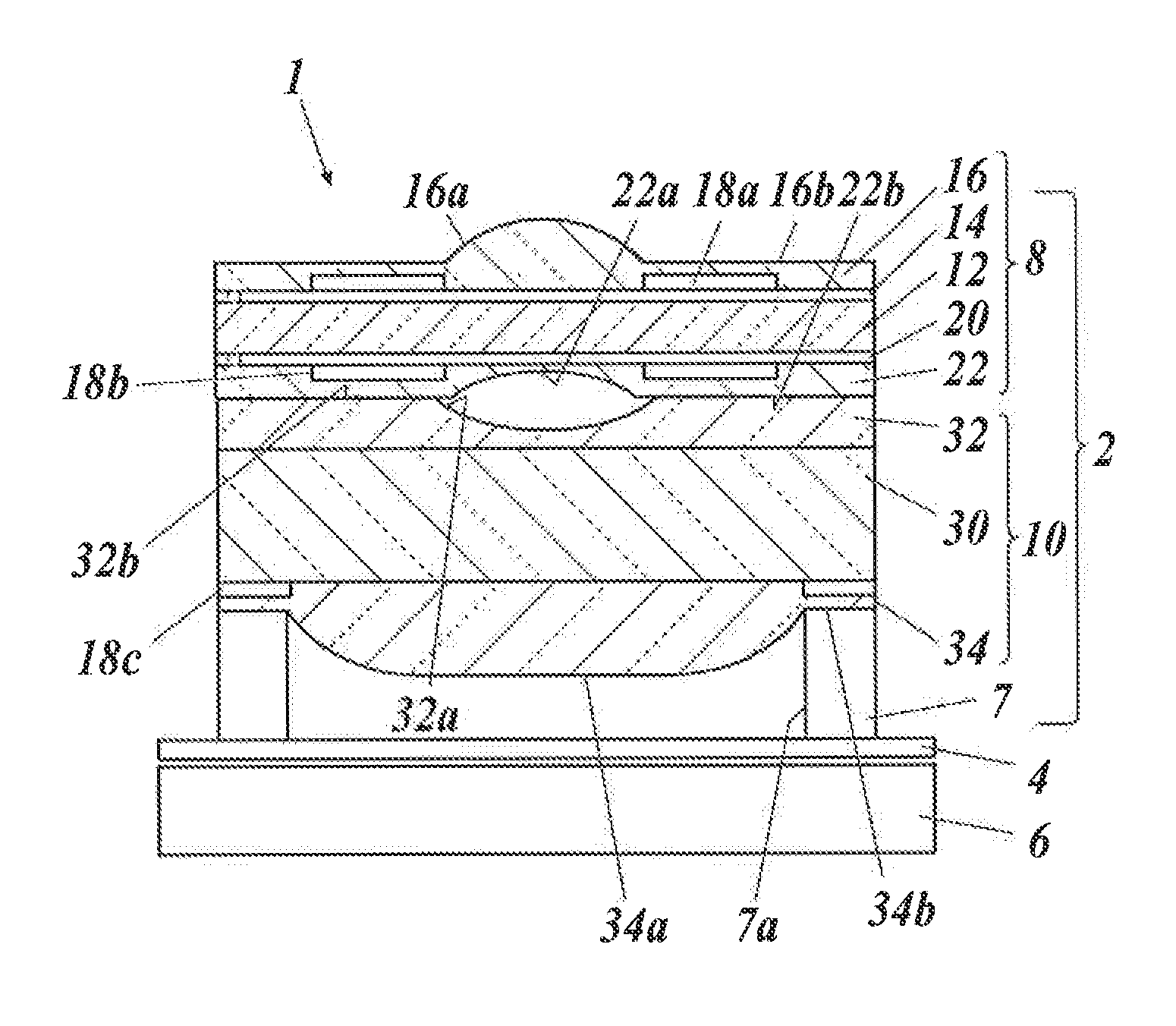
[0024]As shown in FIG. 1, the imaging apparatus 1 includes an imaging lens 2, a cover glass 4 of the imaging element, an imaging element 6, and the like. The cover glass 4 and the imaging element 6 are provided below the imaging lens For example, a CMOS type image sensor is used as the imaging element 6

[0025]The imaging lens 2 includes two groups of lens groups 8 and 10 and a spacer 7.

[0026]The lens group 8 includes a glass substrate 12.

[0027]A resin portion 16 is formed on an upper surface of the glass substrate 12. An aperture 18a is formed between the glass substrate 12 and the resin portion 16. The resin portion 16 includes a convex lens portion 16a and a non-lens portion 16b within the vicinity of the convex lens portion 16a. The convex lens portion 16a and the non-lens portion 16b are formed as one. The convex lens portion 16a has a surface with an aspheric sh...


PUM

PropertyMeasurementUnit
Timeaaaaaaaaaa

Abstract

Disclosed is a method for producing an imaging lens in which a plurality of layers including one or more wafer lenses each provided with a lens portion that is formed from a curable resin are laminated on at least one surface of a substrate. The method for producing an imaging lens comprises, before lamination of the plurality of layers including the wafer lenses, a first lens portion cleaning step wherein carbon dioxide cleaning of the lens portions is carried out by spouting carbon dioxide so as to form dry ice particles and by causing the dry ice particles to hit on the lens portions of the wafer lenses or the vicinities of the lens portions. Consequently, deterioration of optical performance, changes in optical performance due to moisture absorption, and separation of the resin from the substrate can be prevented.

Description

TECHNICAL FIELD[0001]The present invention relates to a method for producing an imaging lens,BACKGROUND ART[0002]Conventionally, in the field of producing an optical lens, a technique being considered is to obtain an optical lens with high heat resistance by providing a lens portion formed from a curable resin, on a glass substrate (for example, see Patent Document 1). As an example of a producing method of an optical lens applying the above technique, there is proposed a method to form what is called a “wafer lens” in which a plurality of optical members made from a curable resin are provided on a surface of a glass substrate and then the glass substrate is cut for each lens portion.[0003]Such wafer lens is outstanding in that a large amount of small optical systems of an imaging apparatus such as a camera for a cellular telephone can be collectively made, however there are also technical problems.[0004]That is, lately, even in cameras for cellular telephones, there is a trend of t...

Claims


Application Information

Patent Timeline
IPC IPC(8): B08B7/00
CPCB24C1/003G02B13/0085G02B3/0062G02B3/0031
Inventor SARUYA, NOBUHIRO
Owner KONICA MINOLTA INC
Why Eureka
Try Eureka