
Optical module and display device

a technology of optical modules and display devices, applied in the field of optical modules, can solve the problems of increasing the production cost of the display device, the inability to impart sufficient light diffusing function to a protective film, and the number of optical sheets

Active Publication Date: 2013-02-14
DAI NIPPON PRINTING CO LTD
View PDF4 Cites 22 Cited by
  • Summary
  • Abstract
  • Description
  • Claims
  • Application Information

AI Technical Summary

Benefits of technology

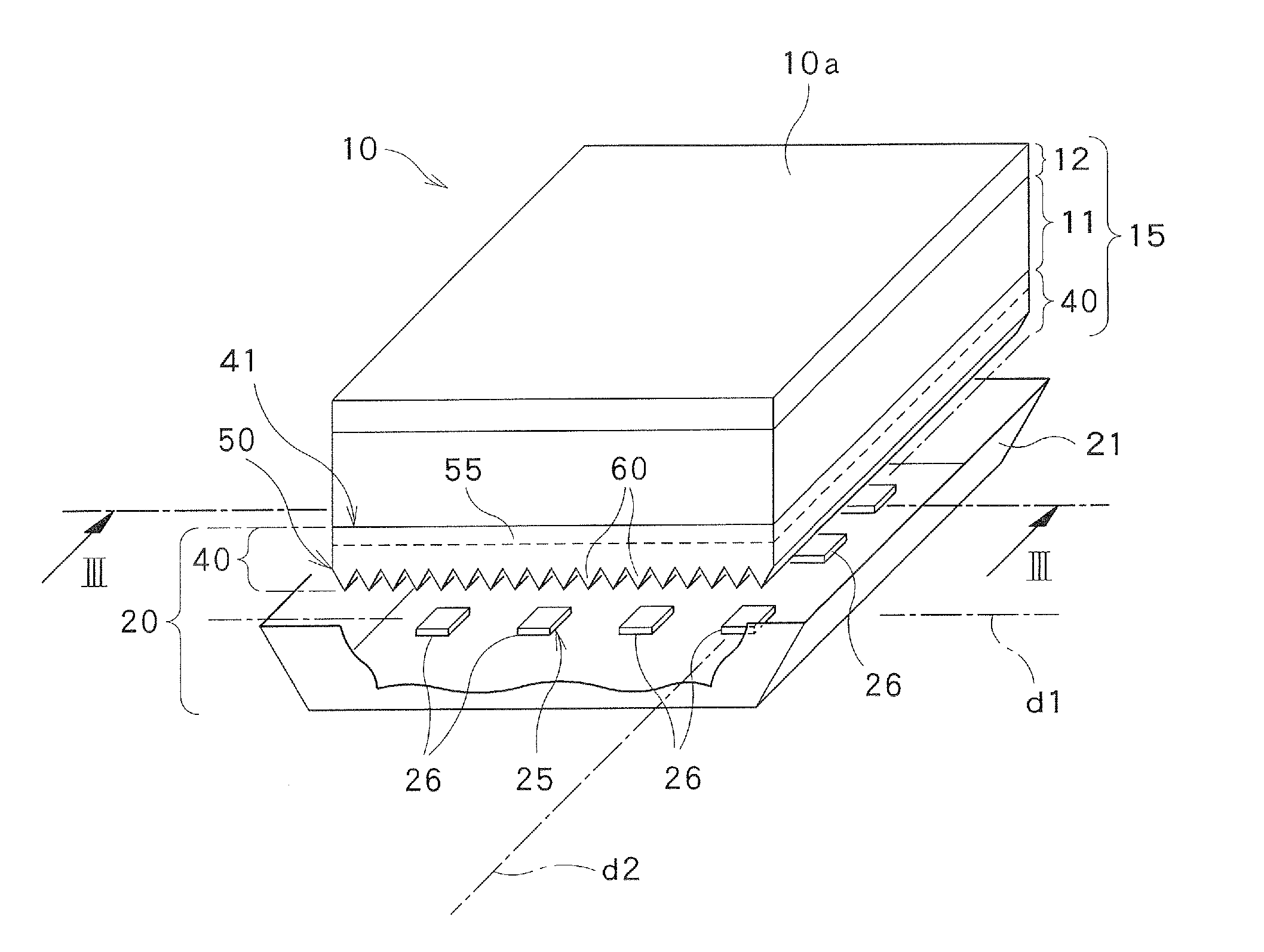
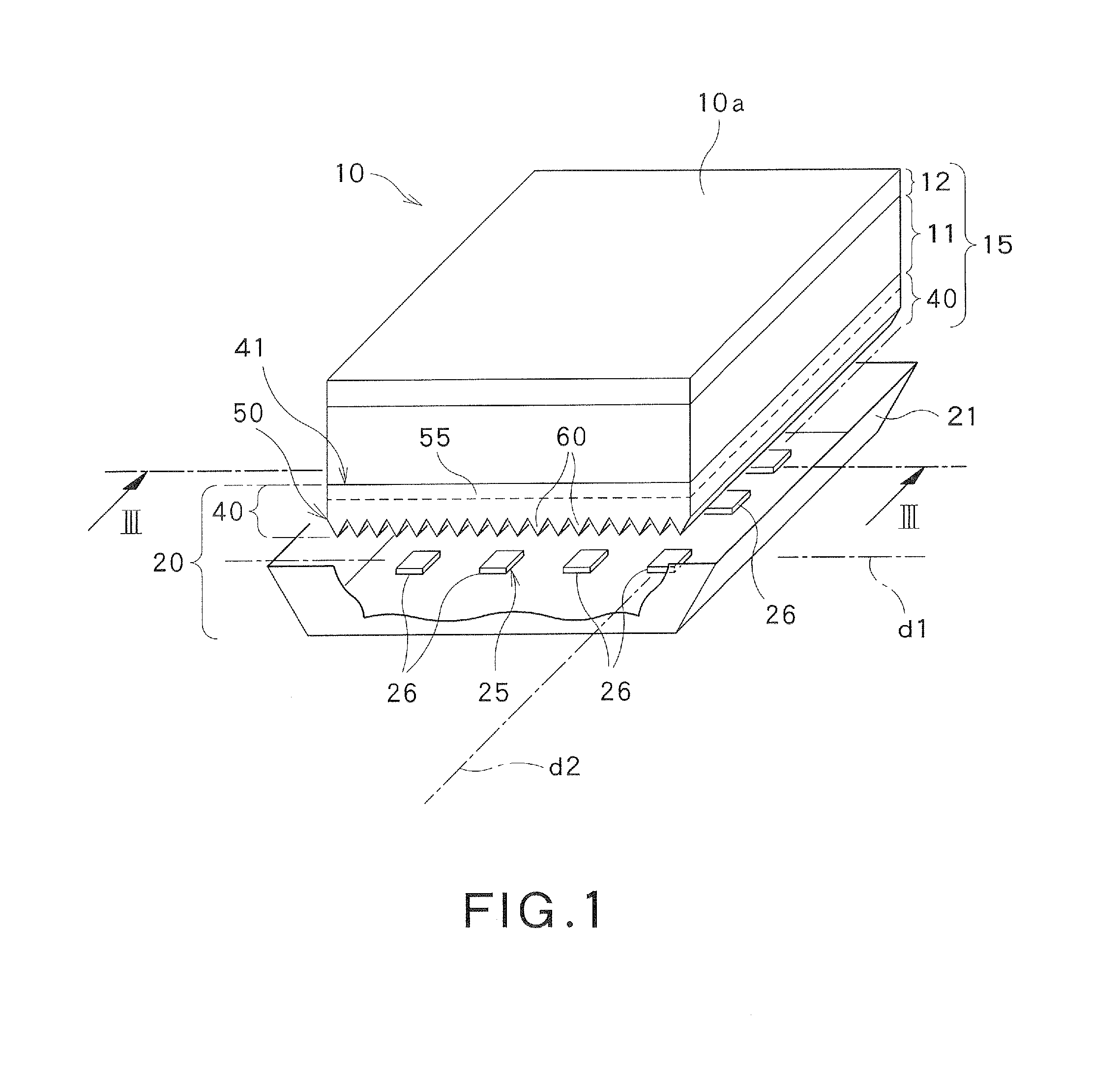
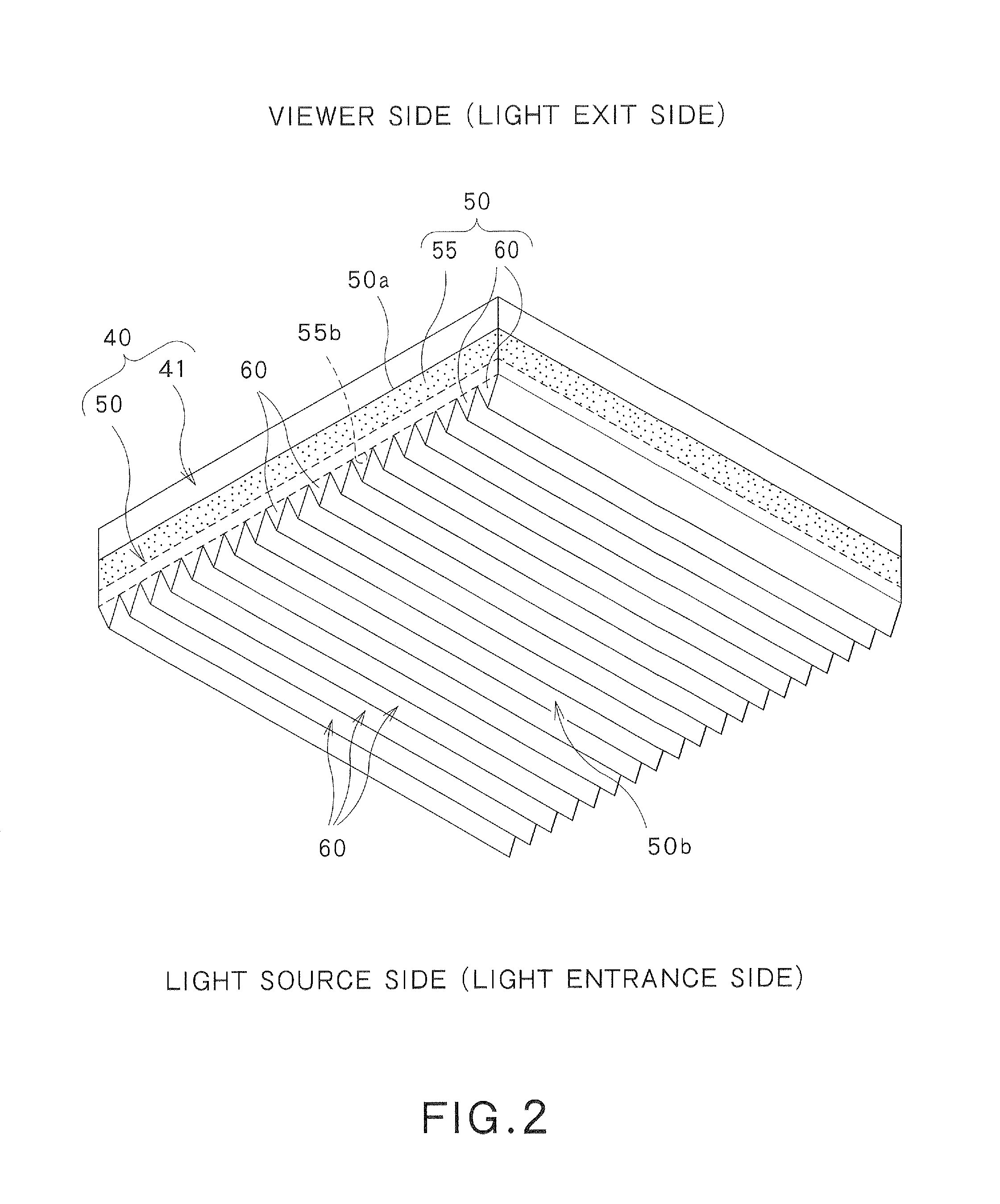
The patent describes a light source for a display panel that includes a protective film with optical elements. The light source has one or more light emitting elements that are positioned in a way that the light emitted by the light source enters the protective film directly. The light source can also be positioned at a distance from the protective film, and the optical elements in the protective film are arranged to form a Fresnel lens that can focus the light emitted by the light source. The patent also describes variations where the light source includes multiple light emitting elements arranged in a line or a closed gap, and a reflective plate may be used to change the direction of the light emitted by the light source before it enters the protective film. These variations can help to reduce brightness variations in the display panel.

Problems solved by technology

In general, the protective film is comprised of a mere light transmissive film due to cost constraints and does not positively exert an optical effect on transmitted light.
However, a sufficient light diffusing function cannot be imparted to a protective film merely by matting the one surface of the protective film.
The inclusion of a number of optical sheets in a surface light source device (display device) may cause various problems.
Firstly, an increase in the number of optical sheets directly increases the production cost of the display device.
Further, assembly of a surface light source device (display device) using a large number of optical sheets necessitates troublesome positioning between the optical sheets and between the optical sheets and light emitters, which may also increase the production cost of the display device.
However, every time light is reflected by an optical sheet, part of the light is absorbed by the optical sheet.
Thus, the use of a number of optical sheets in a surface light source device (display device) will significantly lower the efficiency of the use of light emitted by the light emitters of a light source.
An optical sheet can be heated by heat from light emitters, which may cause deformation of the optical sheet, such as bending, deflection or warpage.
Furthermore, there is a fear of the contact area being visible.
In addition, rubbing between optical sheets can cause scratching in the sheet(s) or produce debris, leading to poor display image quality.

Method used


Image

  • Optical module and display device
  • Optical module and display device
  • Optical module and display device

Examples


experimental examples

[0209]Experiments were conducted to evaluate the effects of the display device 10, the optical module 20, the polarizing plate 40 and the protective film 50 which have been described hereinabove. The particulars of the experiments are as follows.

[0210][Research 1]

[0211]An angular distribution of luminance was simulated for an optical module in which a protective film according to the above-described embodiment, having a light condensing function and a light diffusing function, is joined to a polarizer, and for an optical sheet which uses a light diffusing sheet and a light condensing sheet both as a separate member not joined to a polarizer. LightTools, available from Synopsys, Inc., the United States, was used as simulation soft wafer.

[0212]The direct-light type optical modules shown in FIGS. 42 and 43, referred to as models 1 and 2, respectively, and the edge-light type optical modules shown in FIGS. 44 and 45, referred to as models 3 and 4, respectively, were set as simulation ob...


PUM


Abstract

An optical module (20) includes a polarizing plate (40) and a light emitter (26) disposed in a position facing the polarizing plate. The polarizing plate includes a polarizer (41) and a protective film (50) joined to the polarizer (41). The protective film has a light control function that changes the traveling direction of light. The light emitter is disposed in a position directly facing the protective film of the polarizing plate.

Description

TECHNICAL FIELD[0001]The present invention relates to an optical module including a polarizing plate including a polarizer, and a light emitter disposed in a position facing the polarizing plate.BACKGROUND ART[0002]An optical module, having a polarizing plate including a polarizer, and a light emitter(s) disposed in a position facing the polarizing plate, is incorporated and used in an optical device these days. Such an optical module is typically used in a display device, in particular a liquid crystal display device. The liquid crystal display device includes a liquid crystal display panel, and a surface light source device which functions as a backlight.[0003]As shown in FIG. 40, the surface light source device includes a light source including light emitters, and a number of optical sheets for changing the traveling direction of light from the light emitters, and is designed to be capable of illuminating the liquid crystal display panel with desired optical characteristics. In t...

Claims


Application Information

Patent Timeline
Patent Type & Authority Applications(United States)
IPC IPC(8): F21V9/14
CPCG02B5/0242G02F2001/133607G02B5/3025G02F1/133607
Inventor ASANO, EIJITOMITA, AKIKOKODAMA, DAIJIROGOTO, MASAHIROSEKIGUCHI, HIROSHIYAMAMOTO, HIROSHI
Owner DAI NIPPON PRINTING CO LTD
Learn More