Vertical wind turbine with articulated blades

a technology of wind turbines and blades, applied in wind energy generation, motors, engine fuctions, etc., can solve the problems of reducing the efficiency of this method of catching the wind force, affecting the efficiency of wind turbines, and unable to increase yield

Active Publication Date: 2013-02-14
DULCETTI FILHO FLAVIO FRANCISCO
View PDF5 Cites 10 Cited by
  • Summary
  • Abstract
  • Description
  • Claims
  • Application Information

AI Technical Summary

Benefits of technology

[0039]Another advantage is that when the system opens by the wind pressure, by having symmetric surfaces, it not produces a twist in the support arm or horizontal axis.
[0040]The panels, when it opens symmetrically, due the work of the gears between them, with a counterweight effect, they became restricted almost in a vertical position thr

Problems solved by technology

The aerodynamic surfaces of the blade propeller besides profiting only one component of the wind force, have very small area compared to the circle described by its movement and this configuration cannot increase the yield using multiple propellers to boost the same axis in a catchment area of wind per square meter due to aerodynamic interaction and structural constraints since propellers have great length, are build with heavy materials and are merely fixed in only one point into a spinner and still need to be moved to the control of the

Method used


Image

  • Vertical wind turbine with articulated blades
  • Vertical wind turbine with articulated blades
  • Vertical wind turbine with articulated blades

Examples


first embodiment

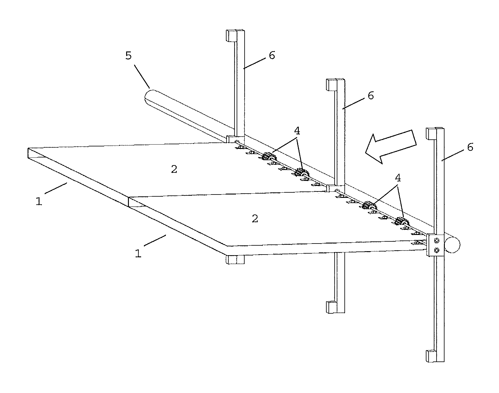
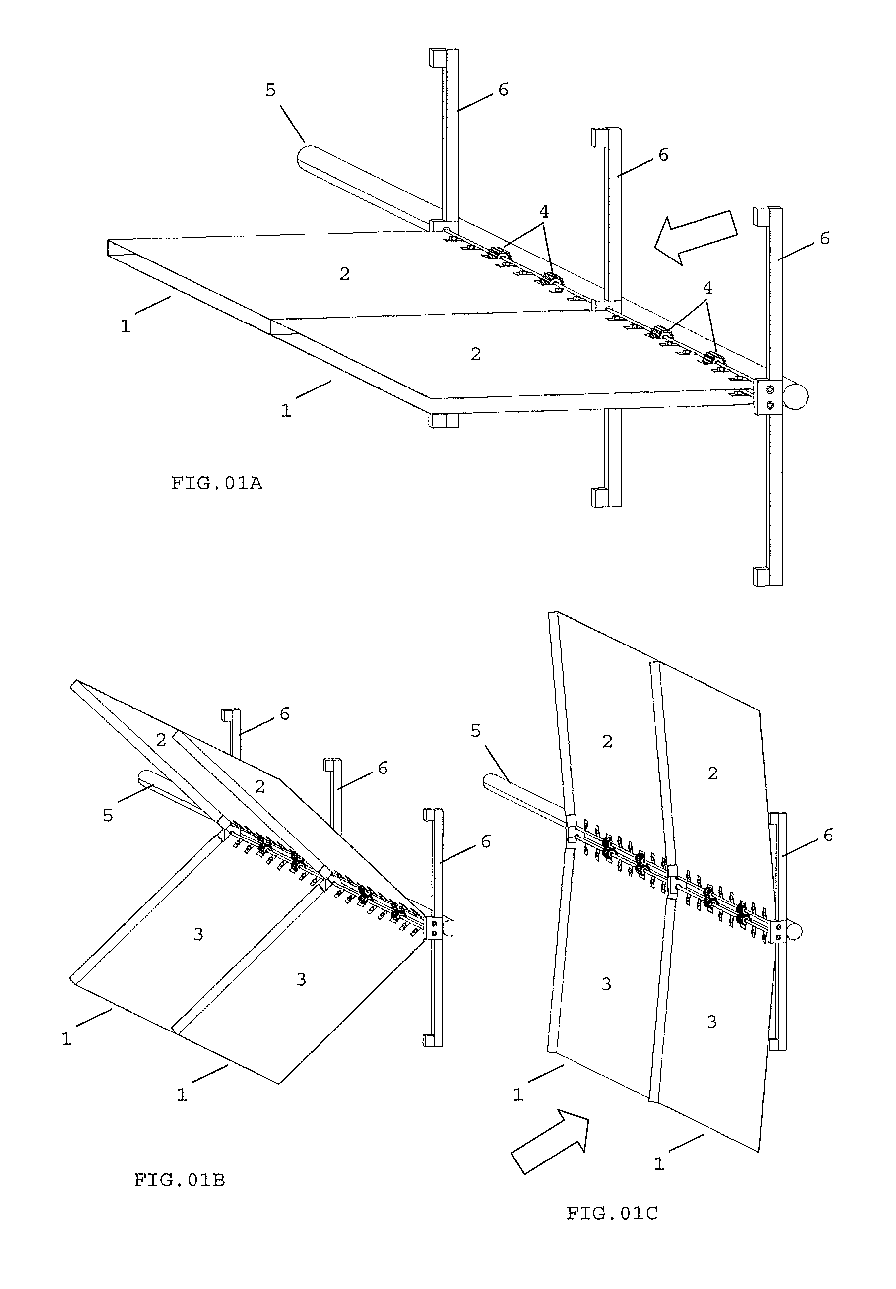
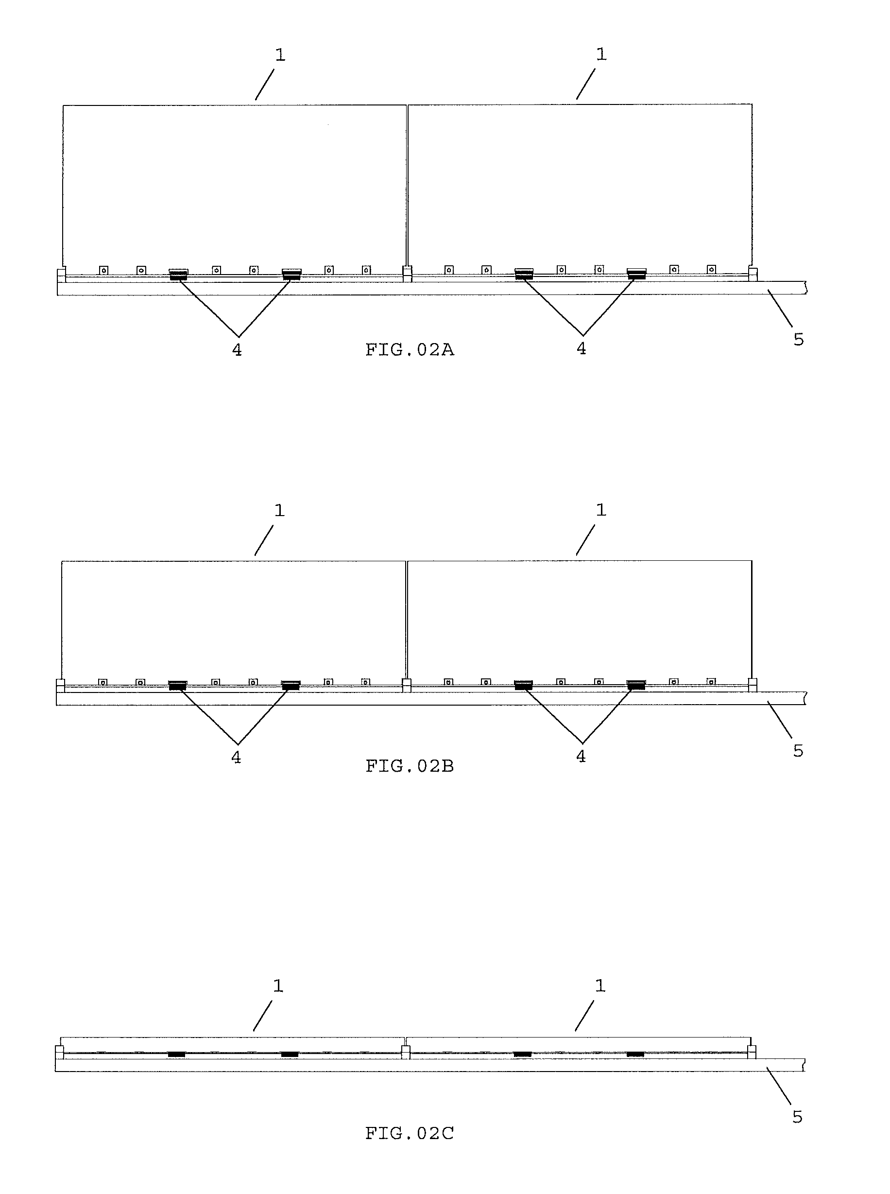
[0113]In the smallest embodiment, illustrated in the FIGS. 14 to 20, is provided a small system with a tubular axis (20) of small caliber to be fixed at the top of a mast or post (21). On this axis rotates a hollow cylindrical cover (22) through bearings (23) and (24) provided with at least one level of crosses (25), where each cross has four metal axis or arms (5) with 90° between them in which shall be fixed at least one aerodynamic panel (1) for each axis or arm.

[0114]The hollow cylindrical cover (22) occupies an extension equivalent to two thirds of the size of the tubular axis (20) and has on its basis a pulley (26) that will operate a small generator (27) that is set on the tubular axis (20) just below of the hollow cylindrical cover (22).

[0115]Optionally, the blades (2) and (3) may contain in its vertex of the open angle (meeting point between the two blades) a canvas or rubber flexible cover (28) in order to reduce the fugue of the wind through its rotating fixing horizontal...

second embodiment

[0117]Also, in this small version, as illustrated in the FIGS. 21 to 31, it may be presented with a different configuration in which the tubular axis (20), on which rotates the hollow cylindrical cover (22) with the sustaining axis or arms (5) and the panels (1) to capture the wind force, down almost until the floor exercising the function of a hollow mast fixed in a cabinet (29) of small height fixed to the ground and scaled with enough internal space to receive not only the tip of the spin axis (30) but also a rotation multiplier box (31), a generator (32), a battery (33) and a voltage converter (34) where

[0118]The spin axis (30) downs inside the sustaining tubular axis (20) of the hollow cylindrical cover (22) and it is coupled by a elastic gasket (35) to the rotation multiplier box (31) that is coupled to a generator (32).

[0119]The battery (33) and the voltage converter (34) can be used in regions where the winds stop sometimes.

[0120]In this configuration the hollow cylindrical ...

third embodiment

[0123]In larger embodiments, as illustrated in FIGS. 32 to 40, for medium and large potencies the system is mounted on a metal or concrete tower (37).

[0124]In this case, the hollow cylindrical cover will not be used. Instead this, a rotating metal structure (38) that comprises the turbine will be used.

[0125]On the top of the tower can be provided, as a first option, an aerogenerator (39) vertically fixed in the concrete or metal structure with its axis (40) facing up on which will be seated the rotating turbine built in metal structure having in its top level (41) the four axis or arms (5) with 90° between them that will be provided with one or more aerodynamic traction panels (1), already described above, in each axis or arm (5).

[0126]From the top of the turbine, that receive the arms of the top-level, down multiple metallic structural elements or columns (42) around the tower to form a new set of four arms, a second lower level, containing the wind force capture aerodynamic panels...


PUM


Abstract

A vertical wind turbine to catch the wind force characterized by its system of aerodynamic panels are provided with blades fixed into horizontal axis that open and close simultaneously and symmetrically upward and downward due the gears like the butterfly wings rotated by 90° of its normal position, it is like opens an umbrella horizontally to receive on one side the wind buoyancy or pressure and in the other side close by the action of the wind. The top and bottom blades works as counterweight one to another both to open and close (flatness) which makes your weight null in relation to the effort of wind to open or close them independent of the self-weight of the blades what propitiate the maximum use of the wind force in the traction side without loss to the return of the blades to the traction position driving a vertical axis.

Description

FIELD OF THE INVENTION[0001]The present invention, as a vertical wind turbine, is applied in the electric power generation by transforming the wind energy into rotational mechanical energy in a controlled way, starting equipments for electric power generation or hydraulic pumps, as well as rotors in general, or anything that can be moved rotationally by the wind force.STATE OF THE ART[0002]The traditional windmills are characterized by having propellers which rotate vertically in parallel to the equipment sustaining post, and directly connected to the generator axis or by shells which rotate in the horizontally direction perpendicular to the post, connected to a vertical rotational axis.[0003]In the case of the propellers, they revolve solely by a component (fraction) of the wind force resultant that, by the angular step variation, provides a perpendicular rotation in relation to the wind direction.[0004]The aerodynamic surfaces of the blade propeller besides profiting only one comp...

Claims


Application Information

Patent Timeline
IPC IPC(8): F03D7/06F03D11/02
CPCF03D3/02F03D3/068F03D11/04Y02E10/74F05B2260/503Y02E10/728F05B2240/218F03D9/11F03D9/25F03D13/20F03D80/70
Inventor DULCETTI FILHO, FLAVIO FRANCISCO
Owner DULCETTI FILHO FLAVIO FRANCISCO
Why Eureka
Try Eureka