Adhesive film

Inactive Publication Date: 2013-02-14
HITACHI CHEM CO LTD
View PDF5 Cites 22 Cited by
  • Summary
  • Abstract
  • Description
  • Claims
  • Application Information

AI Technical Summary

Benefits of technology

[0009]In this type of adhesive film, the outer edges of the first base material layer and carrier layer, which constitute the outer layer, extend outward beyond the outer edges of the adhesive layer and the second base material layer, which constitute the inner layer. This reliably protects the outer edges of the adhesive layer during storage and transport of the adhesive film. When the adhesive layer is to be attached to an, adherend, the outer edge section of the carrier layer that is extended outward may be gripped for easy release of the carrier layer. The outer edge section of the first base material layer may then be gripped for easy release of the first base material layer. Since the second base material layer thus remains on one side of the adhesive layer, protection of the adhesive layer is maintained by the second base material layer when one side of the adhesive layer is to be attached to an adherend. The second base material layer may then be subsequently released and the other side of the adhesive layer attached to a different adherend so that the adhesive layer is disposed between the pair of adherends.
[0010]The outer edge of the second base material layer is preferably flush with the outer edge of the adhesive layer. Since this will accentuate the difference in releasability between the first base material layer and the second base material layer, it will be possible to more easily release the first base material layer before releasing the second base material layer. Furthe

Problems solved by technology

However, it is difficult to coat adhesive layers to prescribed sizes.
Yet, adhesive films formed in such a manner are considered to be responsible for releasability problems of base material layers from the adhesive layer.
An example of the releasability problems is such that the adhesive layer is pulled toward the first base material layer during release of the first base material layer from the adhesive layer,

Method used


Image

  • Adhesive film
  • Adhesive film
  • Adhesive film

Examples


Example

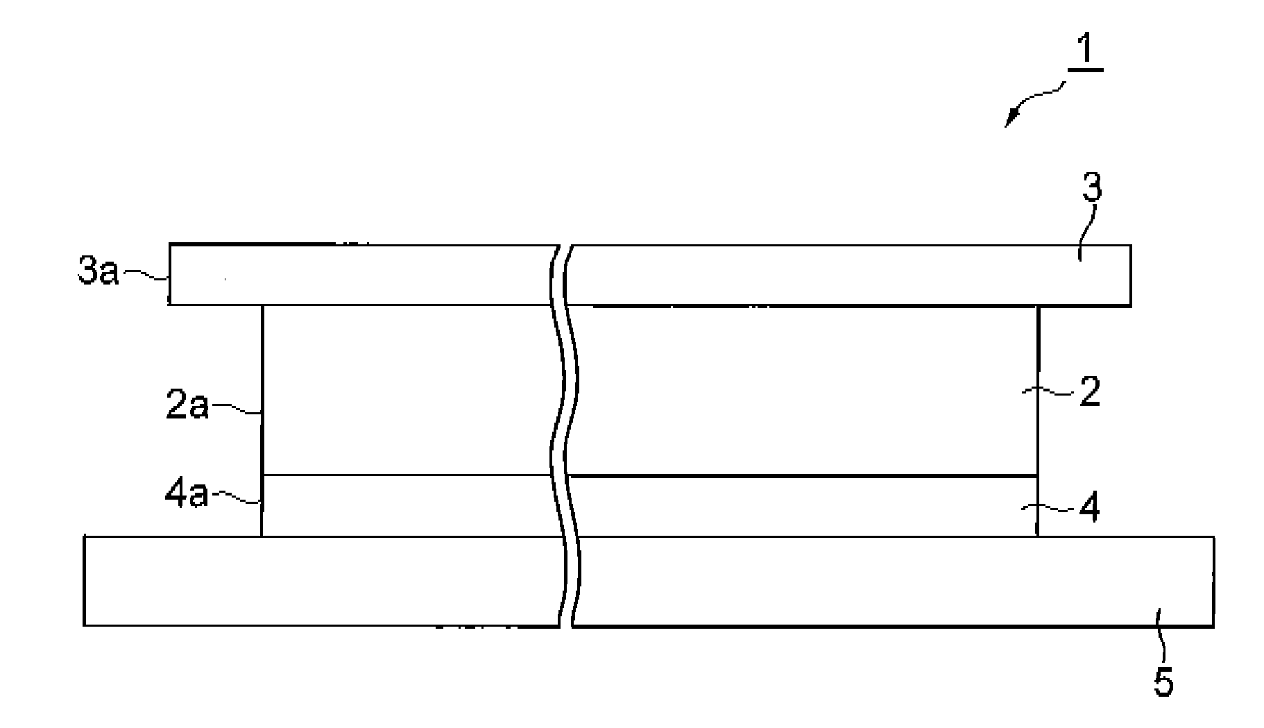
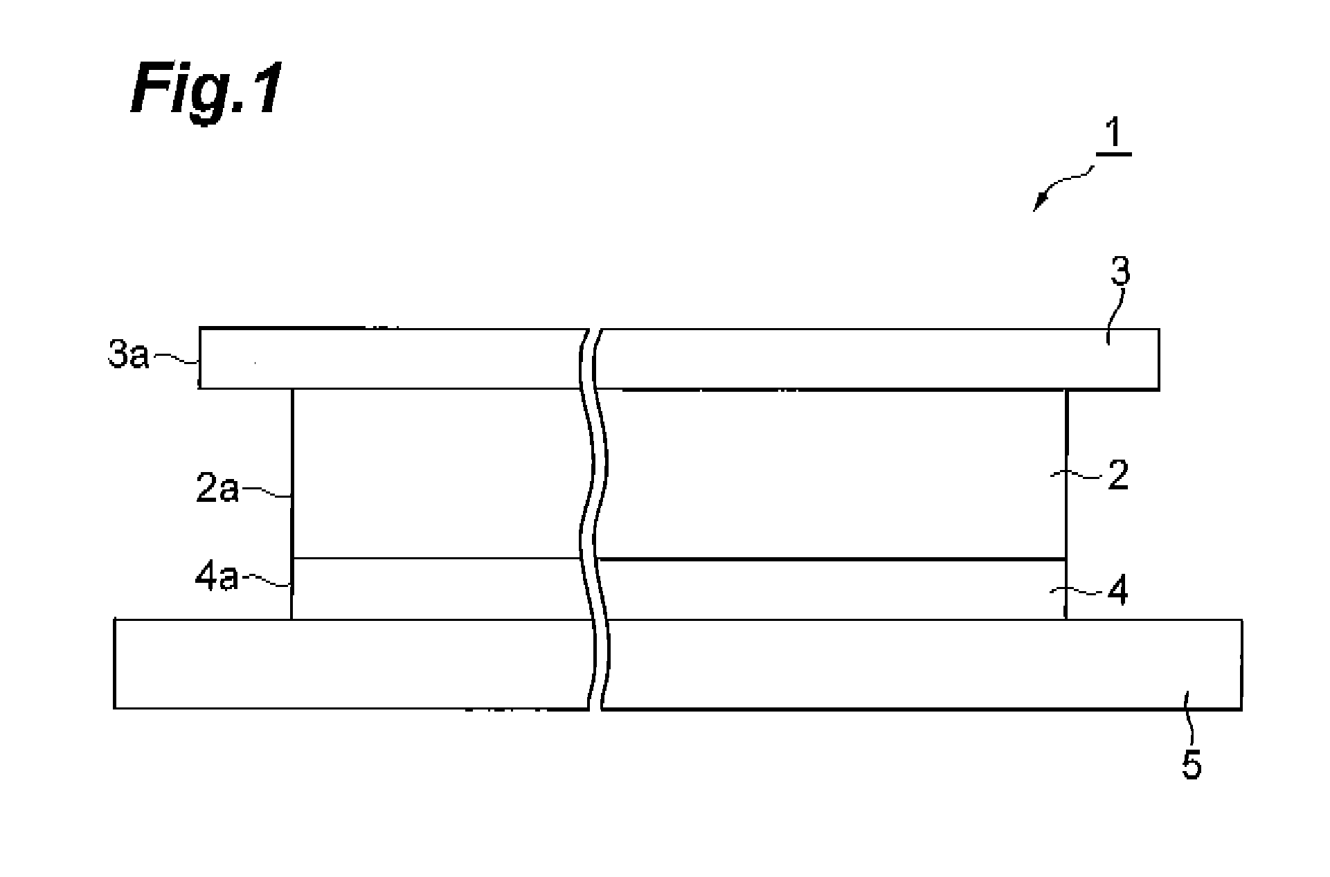
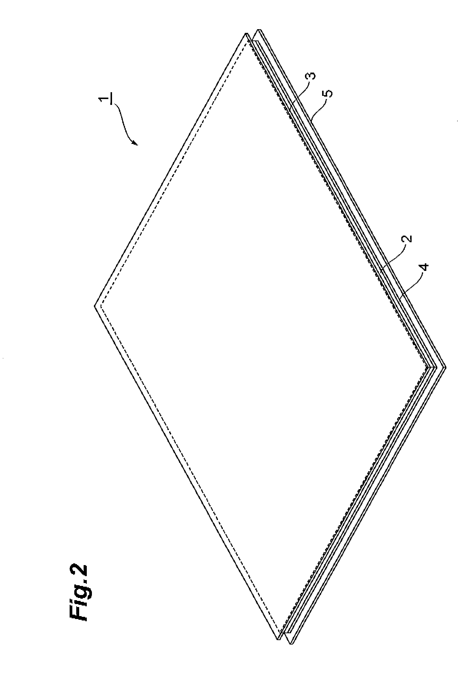
[0030]As shown in FIGS. 1 and 2, the adhesive film 1 of the invention comprises a transparent film-like adhesive layer 2, a light release separator 3 (first base material layer) and a heavy release separator 4 (second base material layer) that are laminated on either side of the adhesive layer 2, and a carrier film 5 (carrier layer) further lamidated on the heavy release separator 4. For assembly of a touch panel display for a portable terminal, for example, the adhesive film 1 serves to provide an adhesive layer 2 between a protective panel and a touch panel, and between the touch panel and a liquid crystal panel.

[0031]The adhesive layer 2 is formed, for example, by an adhesive composition that includes (A) an acrylic acid-based derivative polymer, (B) an acrylic acid-based derivative and (C) a polymerization initiator.

[0032]The (A.) acrylic acid-based derivative polymer may be obtained by polymerizing the (B) acrylic acid-based derivative, and preferably its weight-average molecul...


PUM

PropertyMeasurementUnit
Peel strengthaaaaaaaaaa

Abstract

The adhesive film includes a film-like adhesive layer, a light release separator and a heavy release separator that are laminated on either side of the adhesive layer, and a carrier film further laminated on the heavy release separator. The outer edges of the light release separator and the carrier film forming the outer layer extend outward beyond the outer edge of the adhesive layer and the heavy release separator forming the inner layer. The outer edge sections of the adhesive layer are thereby protected. The outer edge section of the carrier film is gripped and released first, after which the outer edge section of the light release separator is gripped and released, and finally the heavy release separator is released, thereby allowing each separator and the carrier film to be reliably and easily released in the prescribed order.

Description

BACKGROUND OF THE INVENTION[0001]1. Field of the Invention[0002]The present invention relates to an adhesive film.[0003]2. Related Background Art[0004]In recent years, touch panels are being incorporated in the liquid crystal display devices of cellular phones, portable gaming devices, digital cameras, car navigation systems, handheld computers, portable data terminals (PDA) and the like, Such liquid crystal display devices (hereunder also referred to as “touch panel displays”) are constructed in a layered manner, with a protective panel, touch panel and liquid crystal panel in that order, there being disposed transparent adhesive films between the protective panel and touch panel and between the touch panel and liquid crystal panel (see PTL 1, for example). Because such adhesive films help increase the brightness and visibility of the display while also functioning as a shock absorption material, they are indispensable components of the display structure.[0005][PTL 1] Japanese Unex...

Claims


Application Information

Patent Timeline
IPC IPC(8): C09J7/02C09J7/20C09J7/40
CPCC09J7/0225C09J2433/00C09J2203/318C09J2201/606C09J7/20C09J7/40Y10T428/14Y10T428/1476Y10T428/24777Y10T428/2839Y10T428/2848C09J2301/302C09J7/22C09J7/30C09J7/38B32B37/02B32B37/12B32B2307/412B32B2457/202G02F1/1333
Inventor HORIUCHI, KOUHEIURUNO, MICHIOIMAIZUMI, JUNICHISUNOHARA, SEIJINUMAGUCHI, YASUSHI
Owner HITACHI CHEM CO LTD
Why Eureka
Try Eureka