Closed wound drainage system

a closed wound and drainage system technology, applied in wound drains, suction drainage containers, intravenous devices, etc., can solve the problems of unsightly, expensive, awkward to use,

Inactive Publication Date: 2013-02-14
SHAHIM CLINTON FREDERICK
View PDF12 Cites 11 Cited by
  • Summary
  • Abstract
  • Description
  • Claims
  • Application Information

AI Technical Summary

Benefits of technology

[0005]The invention provides a container for use in a closed wound drainage system which includes a body in which is formed a cylinder with a bore, a piston, in sealing contact with the bore, which partly bounds a fluid-receiving volume inside the bore, the piston being movable relative to the

Problems solved by technology

Although, to a greater or lesser extent, devices known to the applicant which are used for draining wounds function satisfactorily th

Method used


Image

  • Closed wound drainage system
  • Closed wound drainage system
  • Closed wound drainage system

Examples


Embodiment Construction

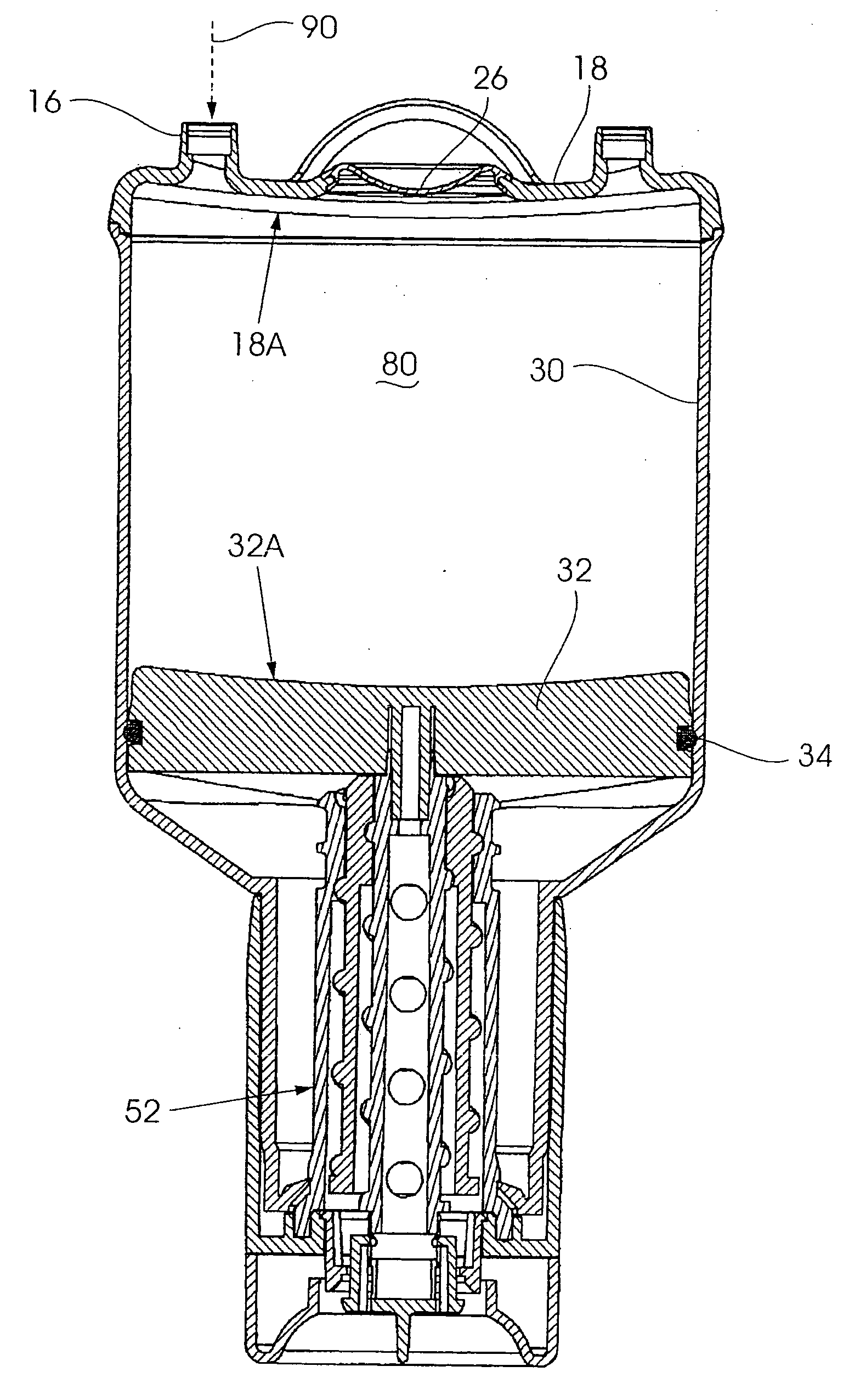
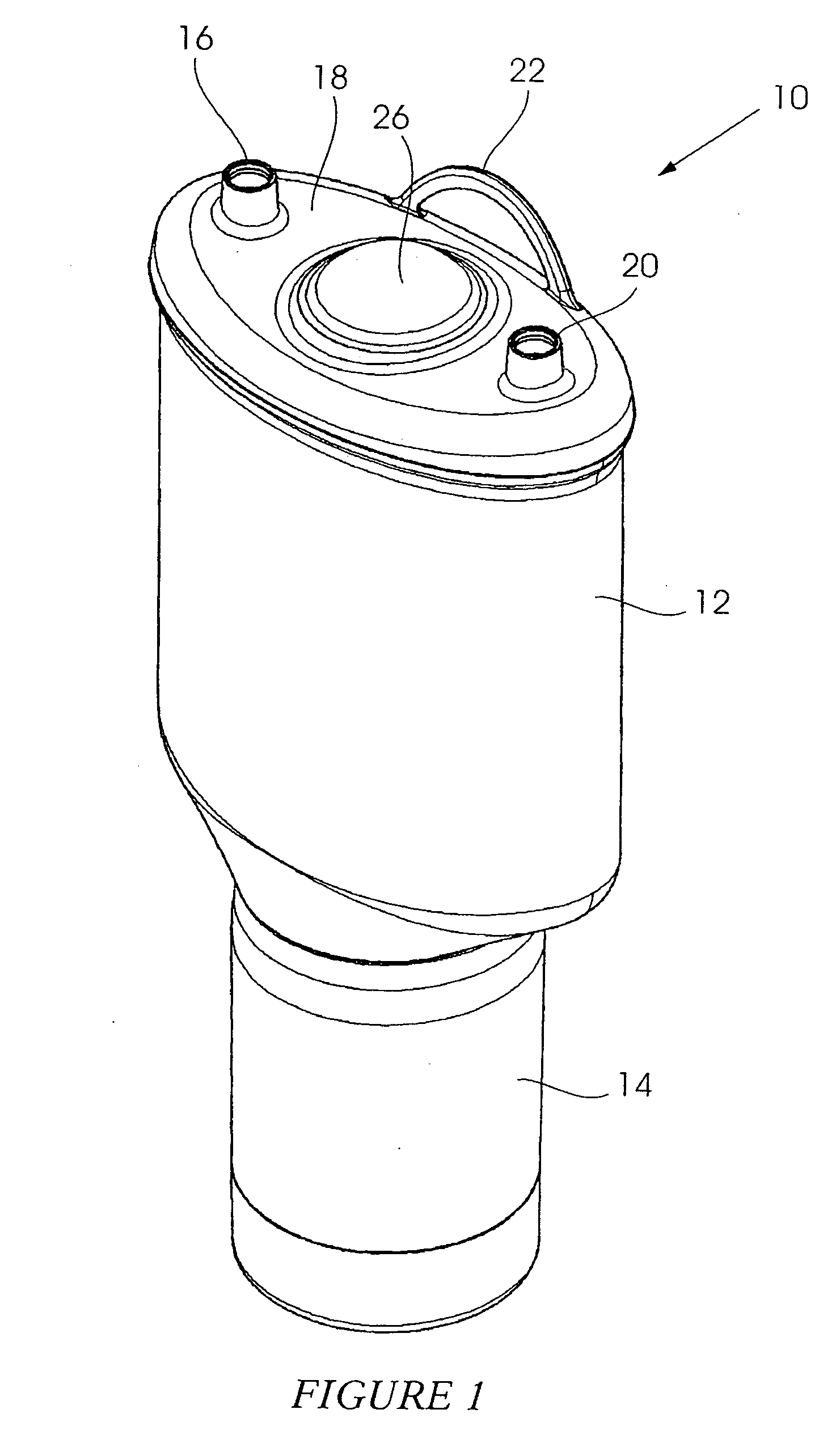
[0019]FIG. 1 of the accompanying drawings is an external view, in perspective, of a container 10 for use in a fluid drainage system. The container has a body 12 and a user-actuable handle 14 at a lower end of the body. A sealable fluid inlet 16 is positioned on one side of a lid 18. A fluid drainage outlet 20, which is also sealable, is positioned on an opposing side of the lid.

[0020]A formation 22 which allows the container to be suspended from overhead structure, not shown, is centrally located on the lid. Below the formation, extending from a circular pedestal 24, is an indicating bellows 26.

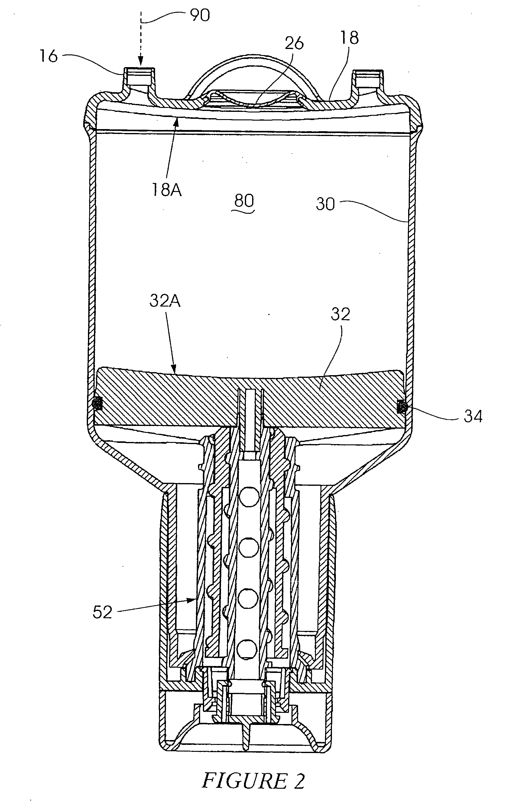
[0021]FIGS. 2 and 3 show the container 10 in cross section in different operative modes while FIG. 4 shows inner components of the container in an exploded configuration.

[0022]The body 12 is oval in shape and, internally, defines an oval-shaped cylindrical bore 30 with a smooth internal surface. A piston 32, of complementary shape to the bore, is slidingly positioned inside the bore. The pist...


PUM


Abstract

A container (10) for a closed wound drainage system which includes a screw-actuated piston (32) sealingly located in a cylinder (30) of non-circular shape to define, inside the cylinder (30), a fluid-receiving volume of variable size.

Description

BACKGROUND OF THE INVENTION[0001]This invention relates to the drainage of body fluids from a closed wound.[0002]It is important to drain fluids from a wound in an injured person or animal, for example during or after an operation. Various techniques have been proposed for this purpose—see for example U.S. Pat. No. 4,599,093, U.S. Pat. No. 4,490,331 and CA2653961.[0003]Although, to a greater or lesser extent, devices known to the applicant which are used for draining wounds function satisfactorily they do, in the applicant's opinion, suffer from one or more disadvantages in that they can be expensive, awkward to use and unsightly.[0004]An object of the invention is to provide a container for use in a closed wound drainage system which, at least partly addresses one or more of the aforementioned requirements.SUMMARY OF INVENTION[0005]The invention provides a container for use in a closed wound drainage system which includes a body in which is formed a cylinder with a bore, a piston, ...

Claims


Application Information

Patent Timeline
IPC IPC(8): A61M27/00
CPCA61M1/0009A61M27/00A61M1/007A61M1/0027A61M2205/073A61M1/67A61M1/732A61M1/815
Inventor SHAHIM, CLINTON FREDERICK
Owner SHAHIM CLINTON FREDERICK
Why Eureka
Try Eureka