Hybrid electric generator set

a generator set and hybrid technology, applied in the field of hybrid electric generator sets, can solve the problems of system inefficiency, engine may have very poor efficiency, momentary droop in frequency and possibly also in voltag

Active Publication Date: 2013-02-14
BAE SYSTEMS CONTROLS INC
View PDF4 Cites 19 Cited by
  • Summary
  • Abstract
  • Description
  • Claims
  • Application Information

AI Technical Summary

Benefits of technology

[0006]In an aspect of the invention, a portable generator system for providing power to a load source includes an engine and a generator. The engine drives the generator to provide a generator alternating current (AC) electrical power output. An energy storage system (ESS) provides an ESS direct current (DC) electrical power output. A first inverter is connected to the generator for receiving the generator AC electrical power output and for providing a DC power output. A second inverter is connected to the first inverter and the ESS for receiving the DC power output from the first inverter and the ESS DC electrical power output for providing an AC power output. A first power mode includes the generator maintaining a first generator power output level corresponding to a specified power requirement of a load source, and the ESS provides an additional first ESS power output level for satisfying the specified power requirement of the load source.

Problems solved by technology

When the engine is not running at optimum speed for a given load, the engine may have very poor efficiency.
When there is low output load, or no output load, a large portion of fuel consumption is required to maintain a moderate to high engine speed and thus makes the system very inefficient.
Additionally, another shortcoming of known generator sets occurs when the power system experiences a large instantaneous load such as from a large motor or heating element, the engine cannot respond instantly, resulting in a momentary droop in frequency and possibly also in voltage, depending on the voltage regulation system.

Method used


Image

  • Hybrid electric generator set
  • Hybrid electric generator set
  • Hybrid electric generator set

Examples


Embodiment Construction

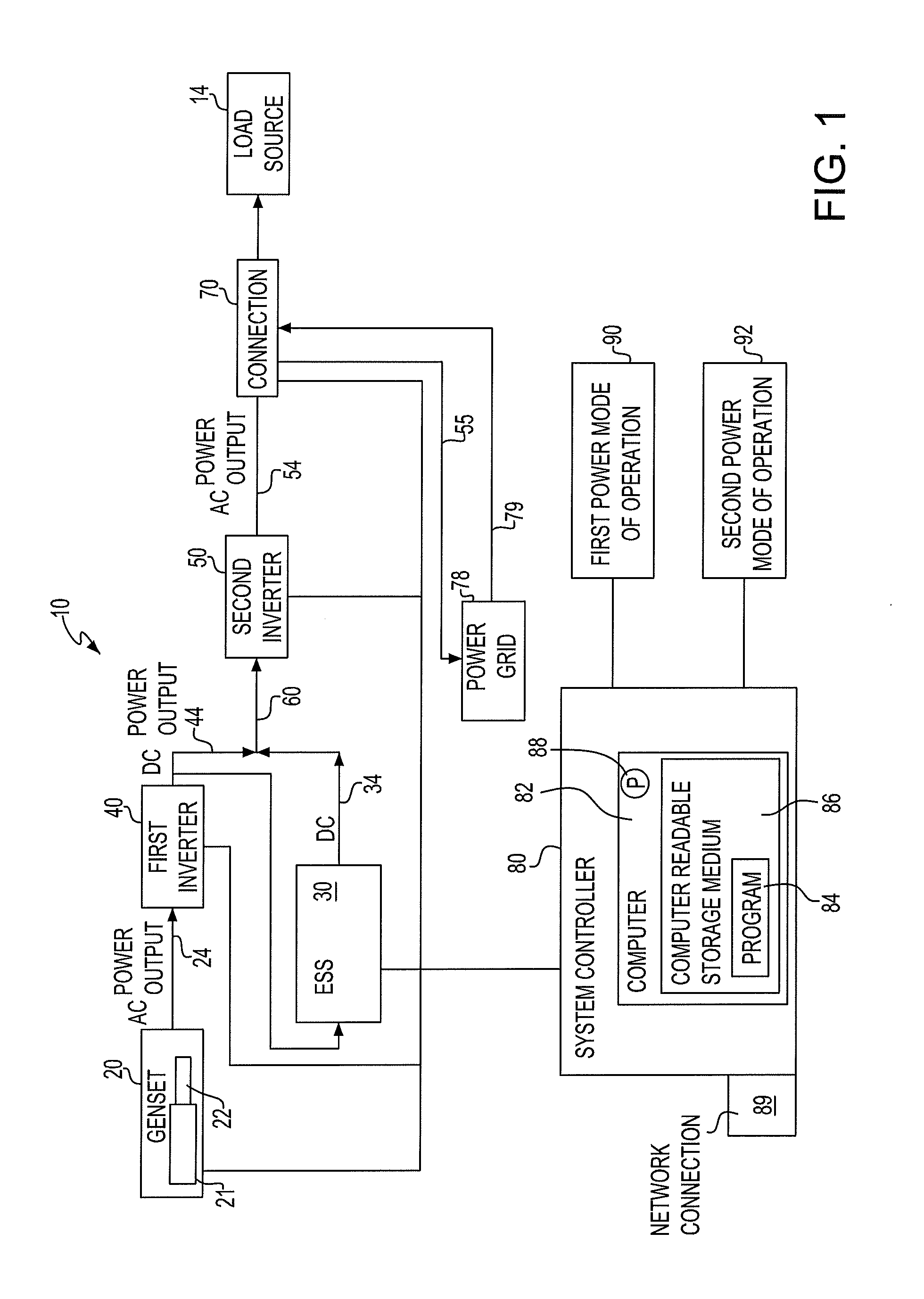
[0010]Referring to FIG. 1, in an embodiment of the invention, a portable generator system 10 provides power to a load source 14. The system 10 includes a generator set 20 which includes a motor or engine 21, for example a diesel engine, which powers a generator 22 to provide an alternating current (AC) electrical power output 24 from the generator 22. For example, the generator 22 may be a permanent magnet generator. An energy storage system (ESS) 30 provides a direct current (DC) electrical power output 34 from the ESS 30. The ESS may include lithium ion batteries. A first inverter 40 is connected to the generator 22 for receiving the AC electrical power output 24, and provides a DC power output 44. The DC power output 44 from the first inverter may also recharge the ESS. Thereby, the generator system may be considered a hybrid electric generator. The ESS may also alternatively include ultra-capacitors, lead-acid batteries, and other energy storage mediums. The ultra-capacitor may ...


PUM


Abstract

A portable generator system provides power to a load source including an engine and a generator. The engine drives the generator to provide a generator alternating current (AC) electrical power output. An energy storage system (ESS) provides an ESS direct current (DC) electrical power output. A first inverter is connected to the generator for receiving the generator AC electrical power output and for providing a DC power output. A second inverter is connected to the first inverter and the ESS for receiving the DC power output from the first inverter and the ESS DC electrical power output for providing an AC power output. A first power mode includes the generator maintaining a first generator power output level corresponding to a specified power requirement of a load source, and the ESS providing an additional first ESS power output level for satisfying the specified power requirement of the load source.

Description

FIELD OF THE INVENTION[0001]The present invention generally relates to electronic generator sets, and more specifically, to a portable generator system including an electronic generator set having an engine and a generator.BACKGROUND OF THE INVENTION[0002]Known are energy storage systems and portable (or auxiliary) power systems for general home use or, on a larger scale, for commercial buildings, for example, hospitals. Also, auxiliary power systems may be used to provide power for many types of equipment, such as lighting, sound systems, amusement park rides, on site machinery or tools, or mobile emergency systems. The power system may include an engine and generator combination (also referred to as a generator set), which may include a diesel or gasoline engine driving a generator which produces a voltage output.[0003]Other power systems may include the use of photovoltaics used directly as a power source, and which may also be fed back to a local power grid, for example, a utili...

Claims


Application Information

Patent Timeline
Patent Type & Authority Applications(United States)
IPC IPC(8): G06F1/26H02J3/32
CPCH02J7/35H02J4/00H02J9/08Y02B10/72H02J9/062Y02B10/70H02J7/34H02K7/1815
Inventor APALENEK, THOMASLU, GORDONPASTERSKI, STEPHENQUIGLEY, THOMAS
Owner BAE SYSTEMS CONTROLS INC
Why Eureka
Try Eureka