Position detection apparatus and image forming apparatus

Active Publication Date: 2013-02-21
CANON KK
View PDF1 Cites 27 Cited by
  • Summary
  • Abstract
  • Description
  • Claims
  • Application Information

AI Technical Summary

Benefits of technology

[0016]According to the present invention, it is possible to detect an edge position of a sheet in th

Problems solved by technology

Therefore, due to influence of a small alignment error of a conveying roller, deformation of a guide plate, and the like, there is a risk that the sheet gradually moves in a sheet width direction perpendicular to a sheet conveying direction and an image formed on the sheet is shifted in the sheet width direction.
Therefore, the cost of the sensor itself increases, causing a problem that the cost of the entire apparatus increases.
To secure the moving distance of the moving holder, for example, it is necessary to enlarge the mo

Method used


Image

  • Position detection apparatus and image forming apparatus
  • Position detection apparatus and image forming apparatus
  • Position detection apparatus and image forming apparatus

Examples


Example

First Embodiment

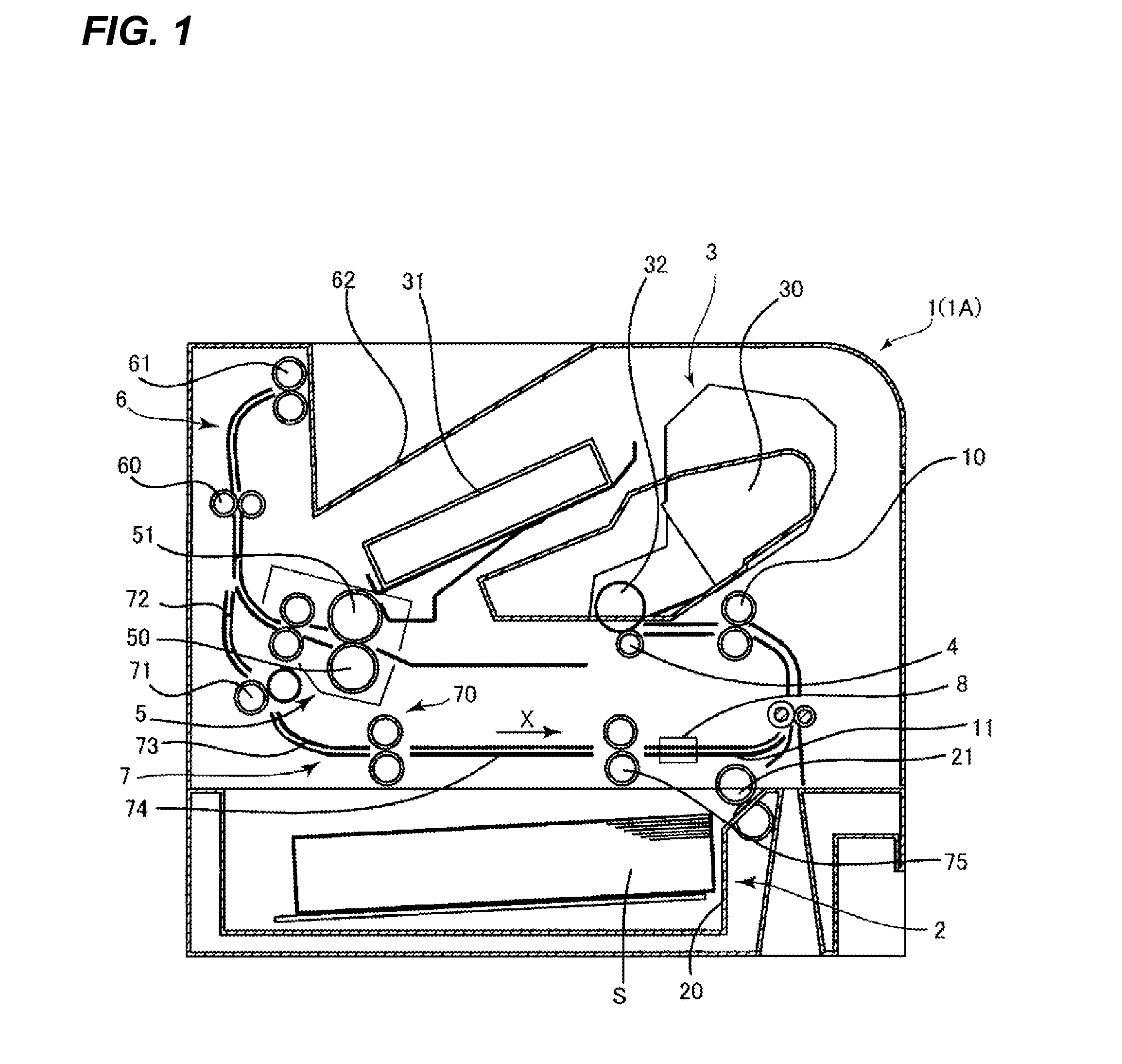
[0028]The laser beam printer 1 according to a first embodiment of the present invention will be described with reference to FIGS. 1 to 9. First, an entire structure of the laser beam printer 1 will be described with reference to FIG. 1 in line with a movement of a sheet on which an image is formed. FIG. 1 is a cross-sectional view schematically illustrating the entire structure of the laser beam printer 1 according to the embodiment of the present invention.

[0029]As illustrated in FIG. 1, the laser beam printer 1 includes a sheet feed portion 2 that feeds a sheet S, an image forming portion 3 that forms an image, a transfer portion 4 that transfers an image to the sheet S fed from the sheet feed portion 2, and a fixing portion 5 that fixes the image transferred to the sheet S. The laser beam printer 1 further includes a discharge portion 6 that discharges the sheet S to which the image is fixed and a reverse conveying portion 7 that reverses the sheet S and conveys t...

Example

Second Embodiment

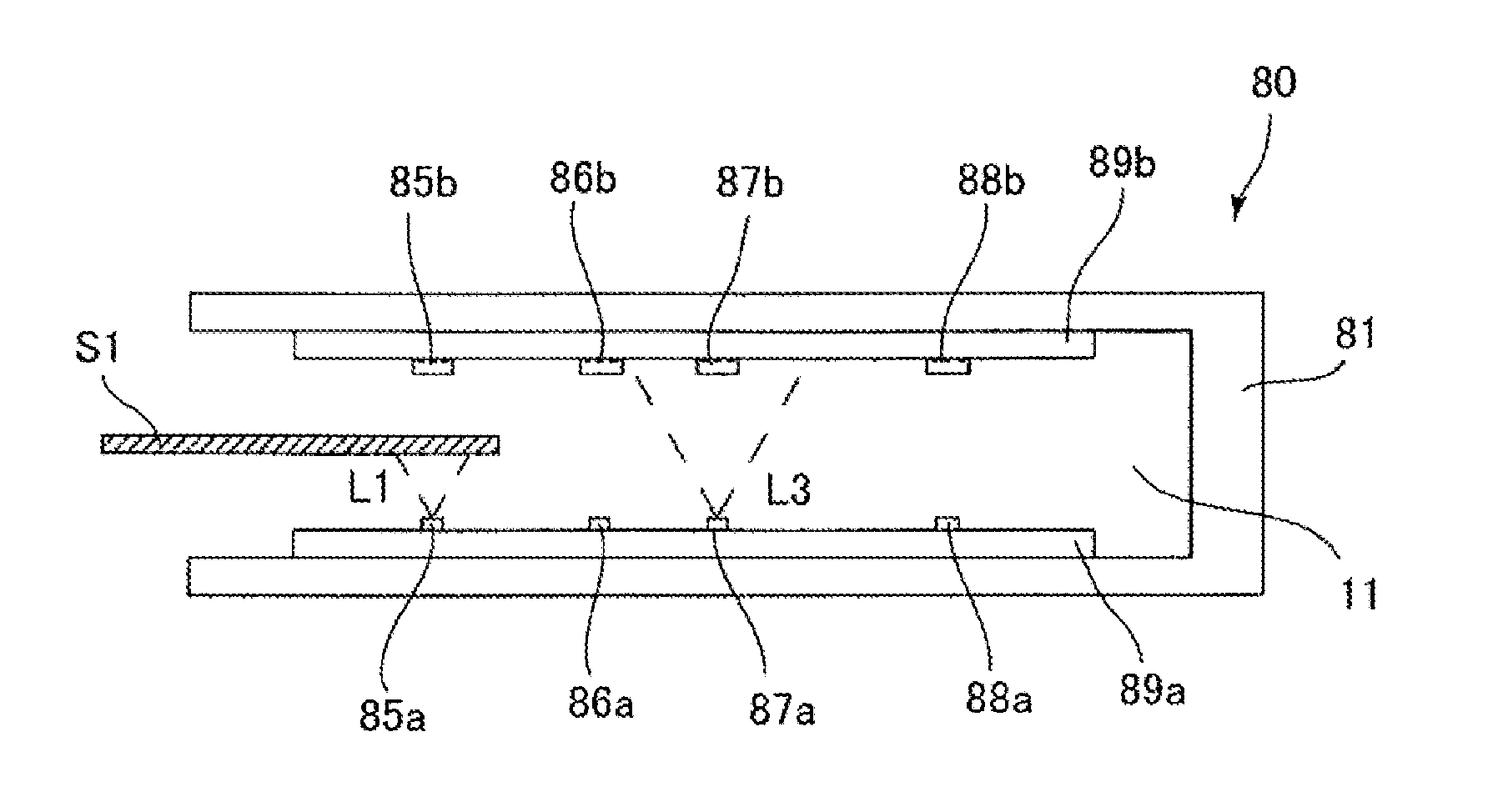
[0063]Next, a laser beam printer 1A according to a second embodiment of the present invention will be described with reference to FIGS. 1 to 9. In the laser beam printer 1A according to the second embodiment, an edge detection controller 90A that controls the first to the fourth pairs of sensors 85 to 88 is different from the edge detection controller 90A of the first embodiment. Therefore, in the second embodiment, the point different from the first embodiment, that is, the edge detection controller 90A, will be mainly described. The same components as those in the laser beam printer 1 according to the first embodiment are given the same reference numerals and symbols, and the descriptions thereof will not be repeated. In other words, in the second embodiment, the same components as those in the first embodiment have the same effects as those in the first embodiment.

[0064]As illustrated in FIG. 4, the edge detection controller 90A according to the second embodiment...


PUM

PropertyMeasurementUnit
Sizeaaaaaaaaaa

Abstract

A position detection apparatus comprises a sensor unit 80 and a moving holder 81 and a holder drive portion 82. The sensor unit has a plurality of pairs of sensors, each of which includes a light emitting portion held on the first holding surface 81a and a light receiving portion held on a second holding surface 81b as a pair and which are arranged along sheet width direction, and the sensor unit detects the edge position of the sheet S while the holder drive portion moves the moving holder in the sheet width direction and every other light emitting portions in the plurality of pairs of sensors is turned on.

Description

BACKGROUND OF THE INVENTION[0001]1. Field of the Invention[0002]The present invention relates to a position detection apparatus which detects an edge position of a sheet passing through a sheet conveying path and an image forming apparatus including the position detection apparatus.[0003]2. Description of the Related Art[0004]Conventionally, there is an image forming apparatus, such as a copying machine and a printer, having a duplex printing function which forms an image on a first side of a sheet (hereinafter referred to as “simplex printing”) and thereafter reverses the sheet and forms an image on a second side opposite to the first side (hereinafter referred to as “duplex printing”).[0005]When the duplex printing is performed in such an image forming apparatus, a sheet conveying path to a position at which the duplex printing is performed (for example, a path in which a sheet where the simplex printing has been completed is reversed and conveyed to an image forming unit) is long...

Claims


Application Information

Patent Timeline
IPC IPC(8): G01N21/86
CPCG01B11/028G03G15/234B65H2701/1315B65H2557/2423B65H2553/822B65H2511/20B65H2301/33312B65H7/14B65H7/10B65H85/00B65H2555/26B65H2553/81B65H2553/416B65H2553/412B65H2511/51G03G15/6567B41J11/0095B65H2220/01B65H2511/12B65H2511/222B65H2220/03B65H2220/02B65H2220/11B65H2511/514B65H2553/82
Inventor MISAO, YOJI
Owner CANON KK
Why Eureka
Try Eureka