Wireless power receiver for controlling wireless power by using switch

Active Publication Date: 2013-02-21
SAMSUNG ELECTRONICS CO LTD +1
View PDF11 Cites 41 Cited by
  • Summary
  • Abstract
  • Description
  • Claims
  • Application Information

AI Technical Summary

Benefits of technology

[0017]Embodiments of the present invention provide a wireless power receiver in which a size of received wireless power is adjusted by periodical short-circuiting and disconnection of a switch. Accordingly, it is possible to manufacture a smaller and lighter wireless power receiver as compared to a conventional DC-DC converting circuit, and significantly reduce a number o

Problems solved by technology

However, since the contact terminal protrudes outwardly in such a contact type charging scheme, the contact terminal is easily contaminated by foreign substances and thus the battery charging is not correctly performed.
Further, battery charging may not be correctly performed in the case in which the contact terminal is exposed to moisture.
However, it is difficult to implement the DC-DC conve

Method used


Image

  • Wireless power receiver for controlling wireless power by using switch
  • Wireless power receiver for controlling wireless power by using switch
  • Wireless power receiver for controlling wireless power by using switch

Examples


Example

[0032]Hereinafter, embodiments of the present invention will be described with reference to the accompanying drawings. In the following description, the same elements will be designated by the same reference numerals although they are shown in different drawings. Further, in the following description of the present invention, a detailed description of known functions and configurations incorporated herein will be omitted when it may make the subject matter of the present invention rather unclear.

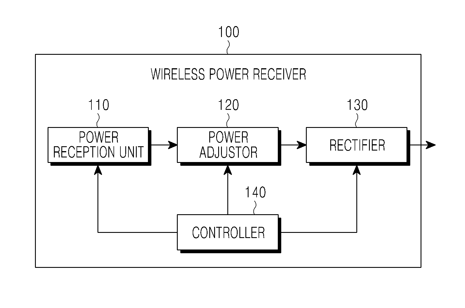
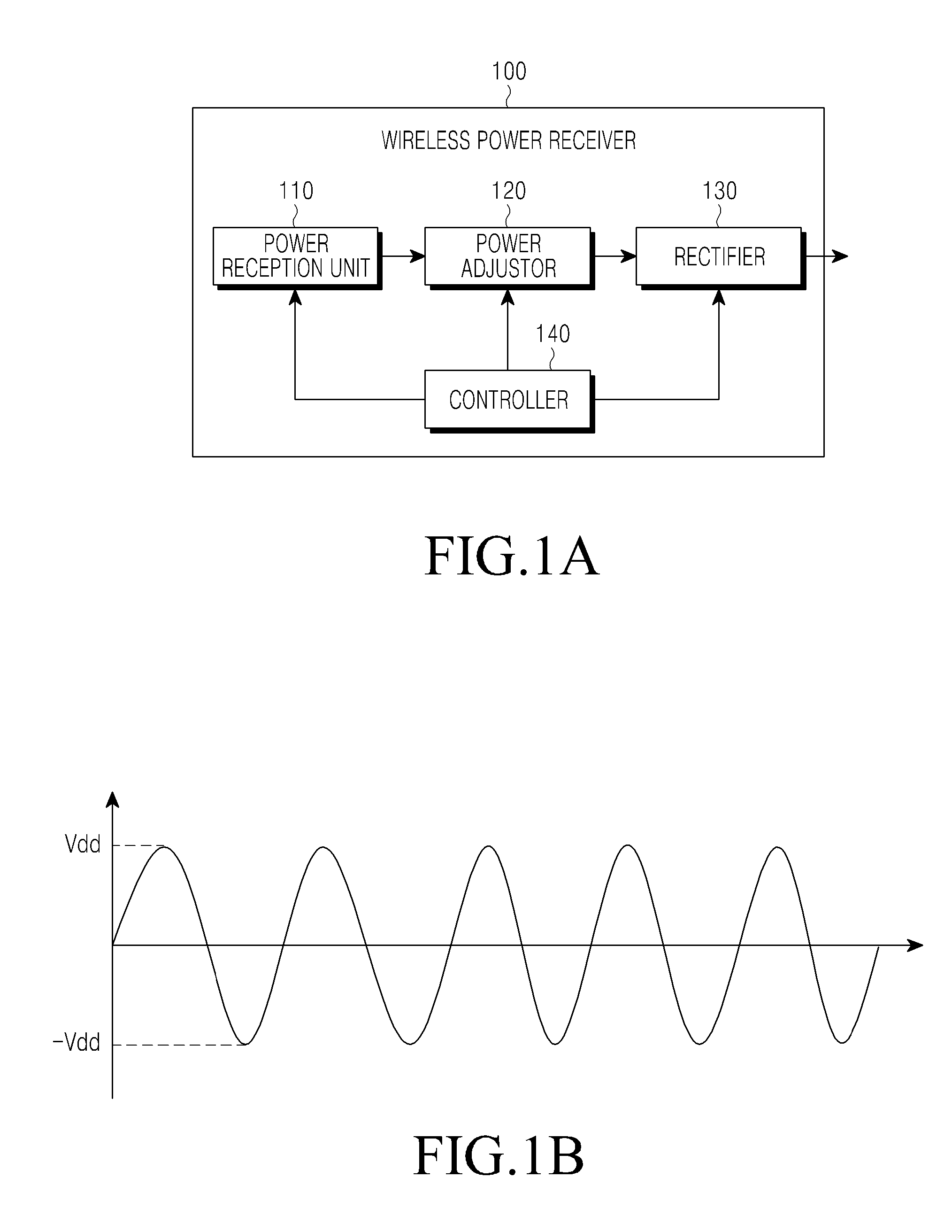
[0033]FIG. 1A is a block diagram illustrating a wireless power receiver according to an embodiment of the present invention.

[0034]A wireless power receiver 100 includes a power reception unit 110, a power adjustor 120, a rectifier 130, and a controller 140.

[0035]The power reception unit 110 receives wireless power provided by a wireless power supplier. The wireless power receiver 100 according to embodiments of the present invention receives wireless power from the wireless power supplier ba...


PUM


Abstract

A wireless power receiver for wirelessly receiving a supply of power from a wireless power supplier is disclosed. The wireless power receiver includes a power reception unit for wirelessly receiving wireless power from the wireless power supplier; a rectifier for rectifying the wireless power into power including a DC waveform; a power adjustor for configuring a closed loop with the power reception unit for a first period and transferring the wireless power to the rectifier for a second period to adjust a size of the wireless power; and a controller for determining the first period and the second period, wherein the power adjustor is electrically connected to the power reception unit and the rectifier.

Description

PRIORITY[0001]This application claims priority under 35 U.S.C. §119(a) to an application filed in the Korean Intellectual Property Office on Aug. 19, 2011 and assigned Serial No. 10-2011-0083072, the entire disclosure of which is incorporated herein by reference.BACKGROUND OF THE INVENTION[0002]1. Field of the Invention[0003]The present invention relates generally to a wireless power receiver, and more particularly to a wireless power receiver for wirelessly receiving power based on an electromagnetic resonance technique.[0004]2. Description of the Related Art[0005]Mobile terminals such as mobile phones, a Personal Digital Assistant (PDA), etc., are powered by rechargeable batteries, and the battery of the mobile terminal is charged through electrical energy by using a charging apparatus. Generally, a separate contact terminal is located outside of the charging apparatus and the battery, and the charging apparatus and the battery are electrically connected to each other through cont...

Claims


Application Information

Patent Timeline
IPC IPC(8): H02J17/00
CPCH02J17/00H02J50/12H02J50/80H02M1/0085H02J7/007H02J50/50H02J50/005H04B5/0037
Inventor YEO, SUNG-KUCHO, GYU-HYEONGPARK, SE-HOKIM, SE-KILEE, YOUNG-MINCHOI, JUN-HAN
Owner SAMSUNG ELECTRONICS CO LTD
Why Eureka
Try Eureka