Imaging apparatus
a technology of imaging apparatus and image sensor, which is applied in the field of imaging apparatus, can solve the problems of increasing the power consumption increasing the heating value of image sensor and camera controller, and reducing the so as to prevent the deterioration of image quality of stereoscopic images caused by temperature differences between imaging units
- Summary
- Abstract
- Description
- Claims
- Application Information
AI Technical Summary
Benefits of technology
Problems solved by technology
Method used
Image
Examples
first embodiment
1. First Embodiment
[0025]1-1. Entire configuration of Imaging Apparatus
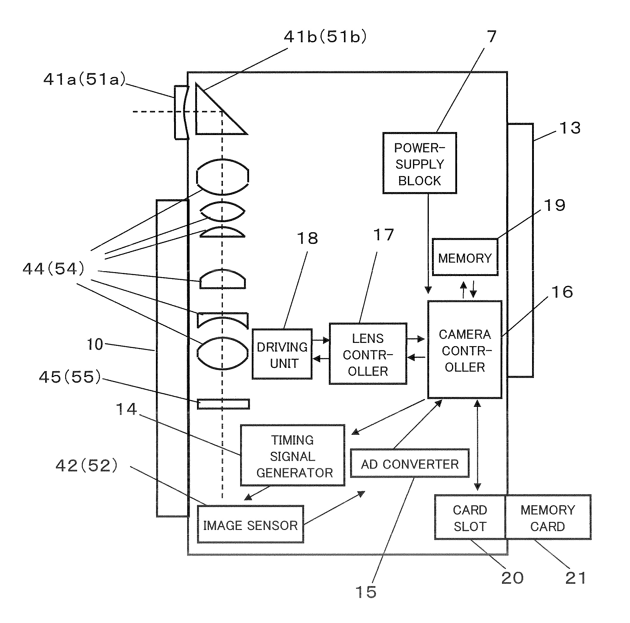
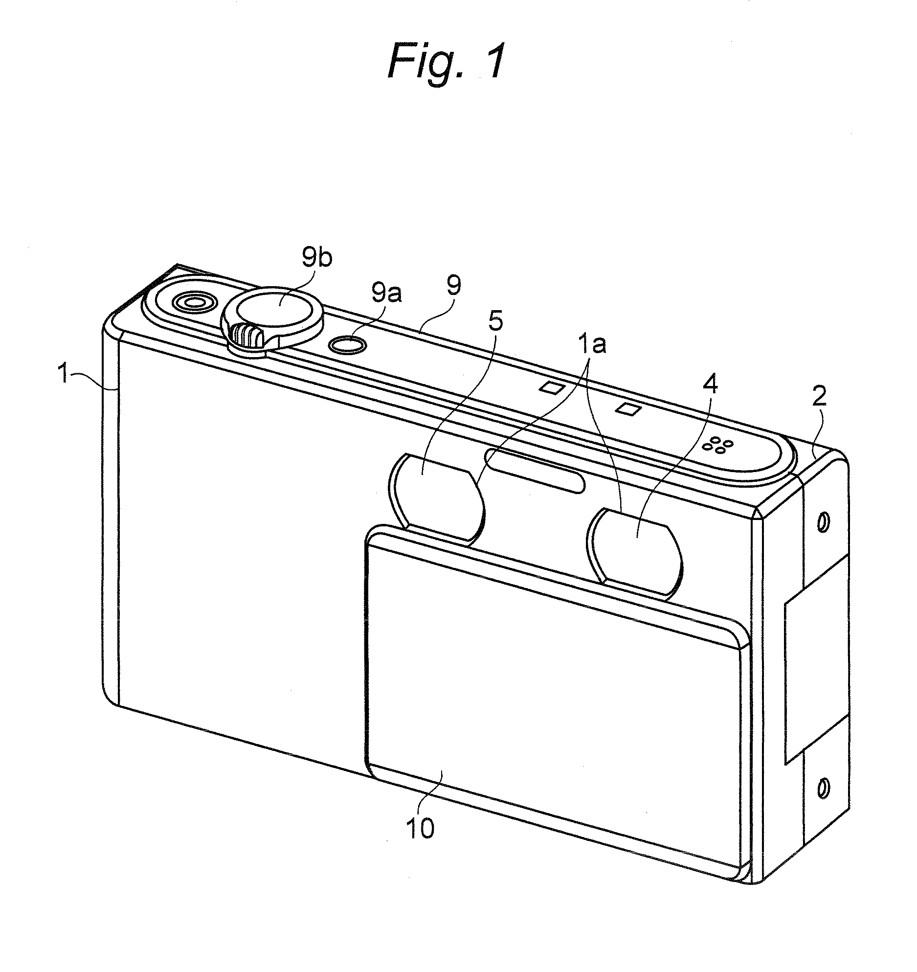
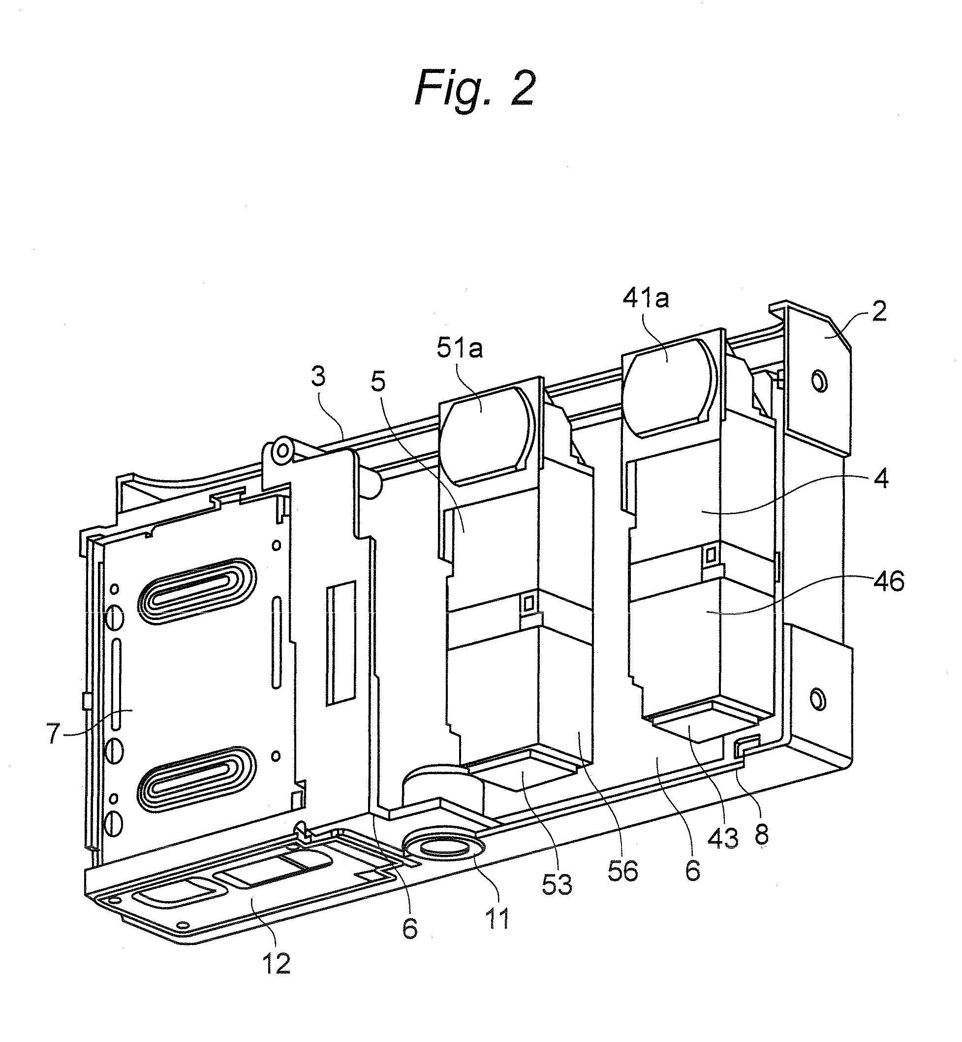
[0026]A digital camera is described below as one example according to an embodiment of the present disclosure. FIG. 1 is a perspective view illustrating the digital camera according to the embodiment. FIG. 2 is a perspective view illustrating an internal constitution from which a front case is removed in FIG. 1.
[0027]As shown in FIGS. 1 and 2, the digital camera is constituted so that a camera body 3 is housed in an exterior case having a front case 1 and a rear case 2. The digital camera according to the embodiment can capture a stereoscopic image that can be stereoscopically viewed. The camera body 3 has a first imaging unit 4 and a second imaging unit 5. The first imaging unit 4 and the second imaging unit 5 are mounted to a metal frame 6 inside the exterior case at an interval. Further, the camera body 3 has a power-supply block 7 that houses a battery (not shown) to be a power supply of the digital camera, a...
second embodiment
2. Second Embodiment
[0059]In the first embodiment, the radiation plate 22 as the thermally-conductive member is one plate composed of a single member. However, the present disclosure is not limited to this. Another example of the radiation plate 22 is described with reference to FIG. 8.
[0060]As shown in FIG. 8, the radiation plates 22a and 22b are joined to the image sensors 42 and 52 of the first imaging unit 4 and the second imaging unit 5, respectively. The radiation plates 22a and 22b are connected by a connecting member 22c having thermal conductivity and flexibility.
[0061]Examples of the connecting member 22c are a graphite sheet, a flexible wiring board on which solid filling of copper foil is formed, and thin aluminum foil having flexibility. Constitutions of the other parts are similar to the first embodiment.
[0062]Even such a constitution, similarly to the first embodiment, provides an effect such that the difference of temperature between the two imaging units 4 and 5 can...
third embodiment
3. Third Embodiment
[0063]Still another constitution for uniformizing the temperatures of the first imaging unit 4 and the second imaging unit 5 is described.
[0064]FIG. 9 is a perspective view illustrating an internal constitution of the digital camera according to a third embodiment. As shown in FIG. 9, the L-shaped radiation plates 23a and 23b are arranged on the image sensors 42 and 52. One End portions of the radiation plates 23a and 23b are thermally joined to the image sensors 42 and 52, and the other end portions are arranged along side surfaces of the imaging units and are arranged between the first imaging unit 4 and the second imaging unit 5. The radiation plates 23a and 23b are formed by, for example, aluminum. Further, a fan 24 for generating a current of air for cooling the radiation plates 23a and 23b are arranged between the radiation plates 23a and 23b in a lower part of the exterior case. Constitutions of the other units are similar to the first embodiment.
[0065]Acco...
PUM
 Abstract
Description
Claims
Application Information
 - R&D
- Intellectual Property
- Life Sciences
- Materials
- Tech Scout
- Unparalleled Data Quality
- Higher Quality Content
- 60% Fewer Hallucinations
Browse by: Latest US Patents, China's latest patents, Technical Efficacy Thesaurus, Application Domain, Technology Topic, Popular Technical Reports.
© 2025 PatSnap. All rights reserved.Legal|Privacy policy|Modern Slavery Act Transparency Statement|Sitemap|About US| Contact US: help@patsnap.com


