System and method for aircraft thermal capacity prediction

a technology of thermal capacity prediction and aircraft, applied in the direction of energy-efficient board measures, navigation instruments, instruments, etc., can solve the problems of insufficient electrical loss removal, insufficient thermal management, and insufficient use of combustor nozzle fuel, etc., to achieve the effect of enhancing the capability of modern aircra

Active Publication Date: 2013-02-21
P C KRAUSE & ASSOC
View PDF11 Cites 4 Cited by
  • Summary
  • Abstract
  • Description
  • Claims
  • Application Information

AI Technical Summary

Benefits of technology

[0014]Disclosed herein is a technique to identify and project the thermal capacity for an aircraft either prior to flight or in real-time during the ...

Problems solved by technology

Although most electrical systems used onboard aircraft are designed to be highly efficient, the sheer magnitude of onboard power demand and unique design aspects of onboard aviation systems lead to considerable thermal management challenges.
This poses significant challenges to the thermal management system, as it has to remove all of the generated waste heat with minimal temperature rise at a minimum of weight and volume.
In addition to the challenge of moving the heat efficiently to the convective surface, the ultimate rejection of heat is a challenge for aviation platforms.
Heating fuel prior to it entering the engine combustor is advantageous to the engine efficiency, although this is limited by the thermal stability of conventional jet fuel which, if compromised, can foul heat transfer surfaces.
While there is a large amount of fuel on-board an aircraft, its use is not evenly distributed over the flight envelope.
Thus the fuel flow to the combustor nozzles rarely matches the electrical loss removal demands required by an MEA.
For instance, an aircraft electrical system often requires significant cooling during idle-descent when electrical loads are relatively high (e.g., from actuation of flight control surfaces), but fuel flow is extremely low.
Using the fuel tank for thermal energy storage is convenient, but also has its limitations.
As the mission progresses and fuel levels are reduced, the high temperature return fuel has an increasingly greater likelihood of raising the temperature of the fuel in the tank.
On the ground, air can be extremely cold or hot.
Although air at high altit...

Method used


Image

  • System and method for aircraft thermal capacity prediction
  • System and method for aircraft thermal capacity prediction
  • System and method for aircraft thermal capacity prediction

Examples


Embodiment Construction

[0021]For the purpose of promoting an understanding of the principles of the invention, reference will now be made to the embodiments illustrated in the drawings and specific language will be used to describe the same. It will nevertheless be understood that no limitation of the scope of the invention is thereby intended. Any alterations and further modifications in the described embodiments, and any further applications of the principles of the invention as described herein are contemplated as would normally occur to one skilled in the art to which the invention relates. One embodiment of the invention is shown in great detail, although it will be apparent to those skilled in the relevant art that some features that are not relevant to the present invention may not be shown for the sake of clarity.

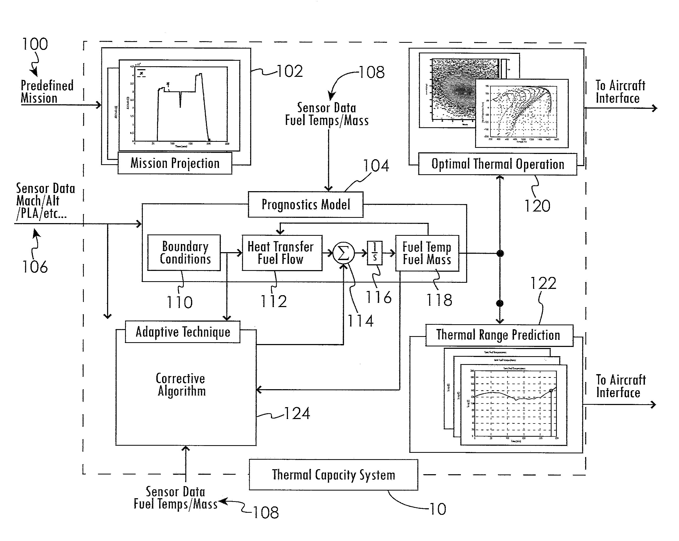
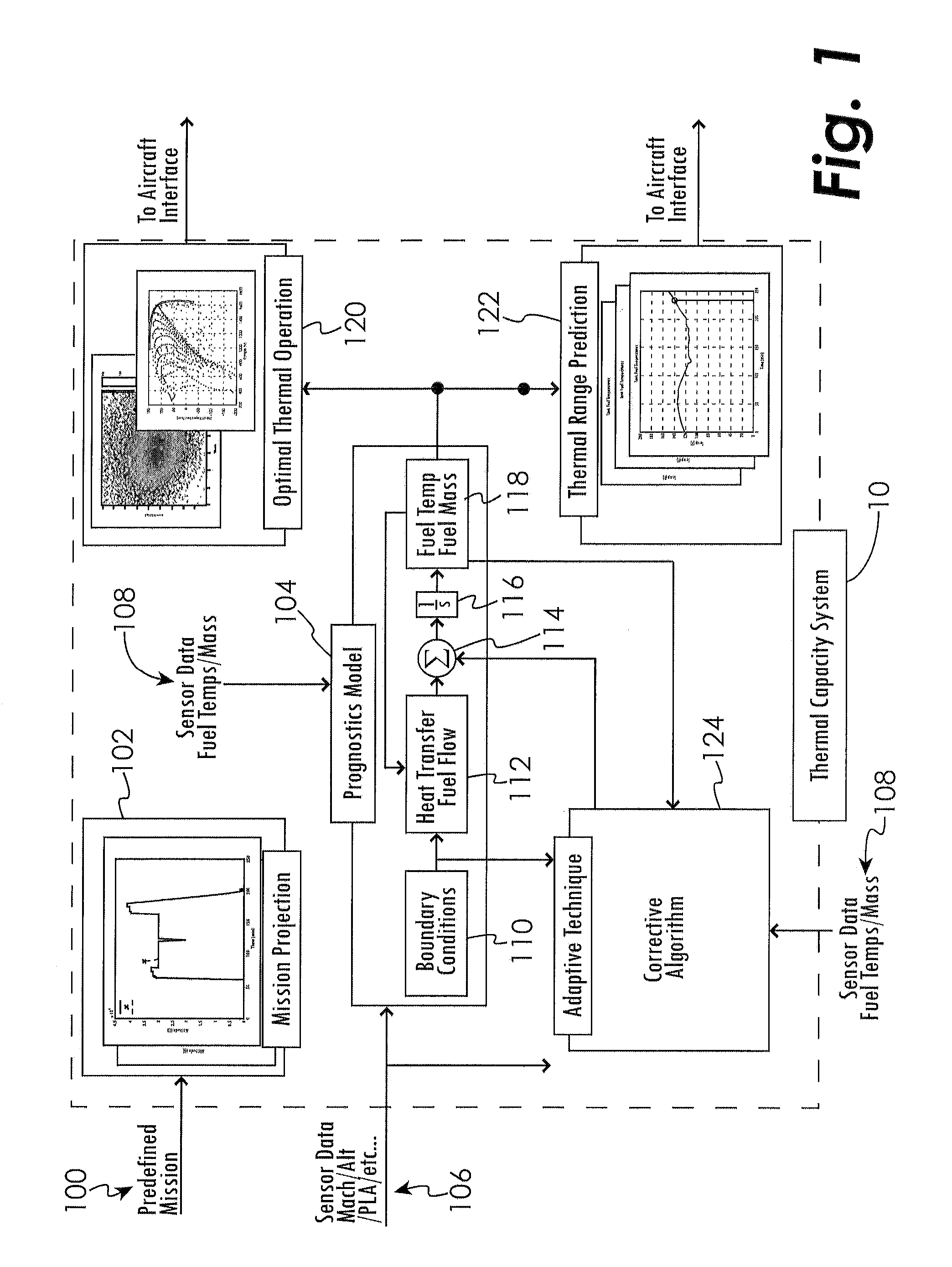
[0022]Disclosed herein are systems and methods to identify and project the thermal capacity for an aircraft either prior to flight and / or in real-time during the flight. A projection of o...


PUM


Abstract

A technique for identifying, projecting, displaying, and enhancing the thermal capacity for an aircraft is disclosed wherein the thermal capacity is defined as the amount of time or range the aircraft can continue until a thermal limit is exceeded.

Description

[0001]The present application claims the benefit of U.S. Provisional Patent Application Ser. No. 61 / 525,004 filed Aug. 18, 20118 entitled “Aircraft Thermal Capacity Prediction / Adaptation” which is hereby incorporated by reference in its entirety.GOVERNMENT RIGHTS CLAUSE[0002]This invention was made with Government support under Contract Number N68335-11-C-0095 awarded by the U.S. Navy. The United States Navy has certain rights in the invention.TECHNICAL FIELD OF THE DISCLOSURE[0003]The present disclosure generally relates to systems and methods for prediction of the performance of a physical system and, more particularly, to systems and methods for aircraft thermal capacity prediction.BACKGROUND OF THE DISCLOSURE[0004]For aviation platforms, achieving the highest performance with the lightest weight systems that exceed the required reliability standards is paramount. Military aircraft often emphasize mission capability as the key objective, while commercial aircraft often emphasize ...

Claims


Application Information

Patent Timeline
IPC IPC(8): B64C19/00G01C23/00
CPCB64D37/34Y02T50/56Y02T50/54Y02T50/50
Inventor MCCARTHY, KEVIN M.WALTERS, ERIC A.HELTZEL, ALEX J.
Owner P C KRAUSE & ASSOC
Why Eureka
Try Eureka