

Mobile Solid Waste Material Collection and Handling Device and Method of Use
- Summary
- Abstract
- Description
- Claims
- Application Information
AI Technical Summary
Benefits of technology
Problems solved by technology
Method used
Image

Examples
Embodiment Construction
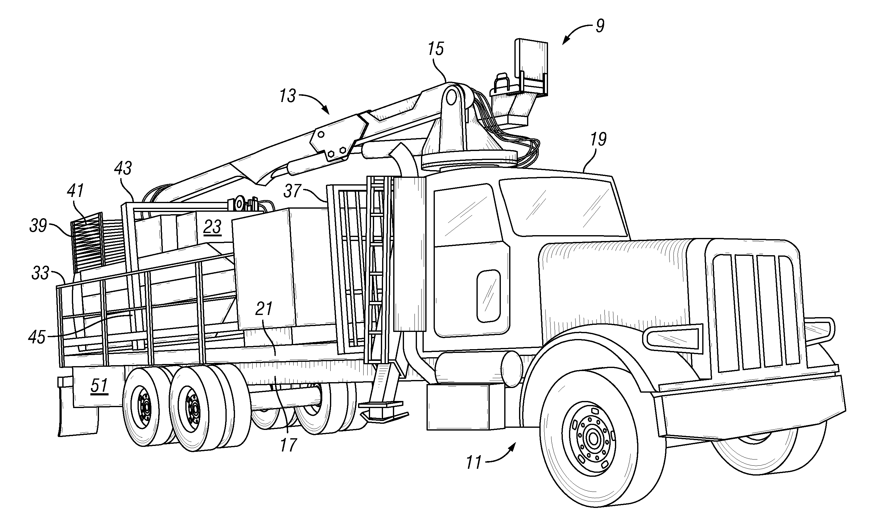
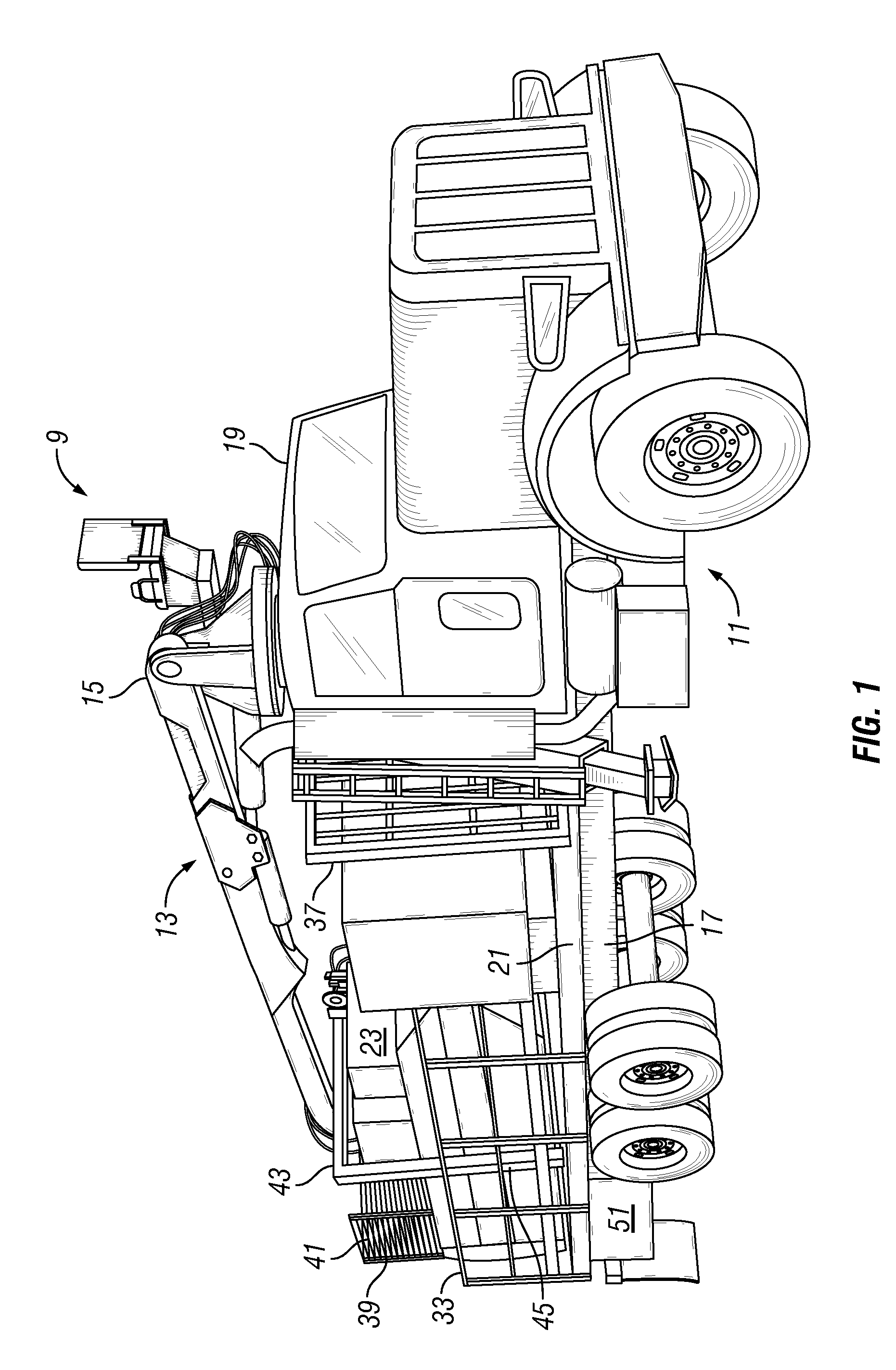
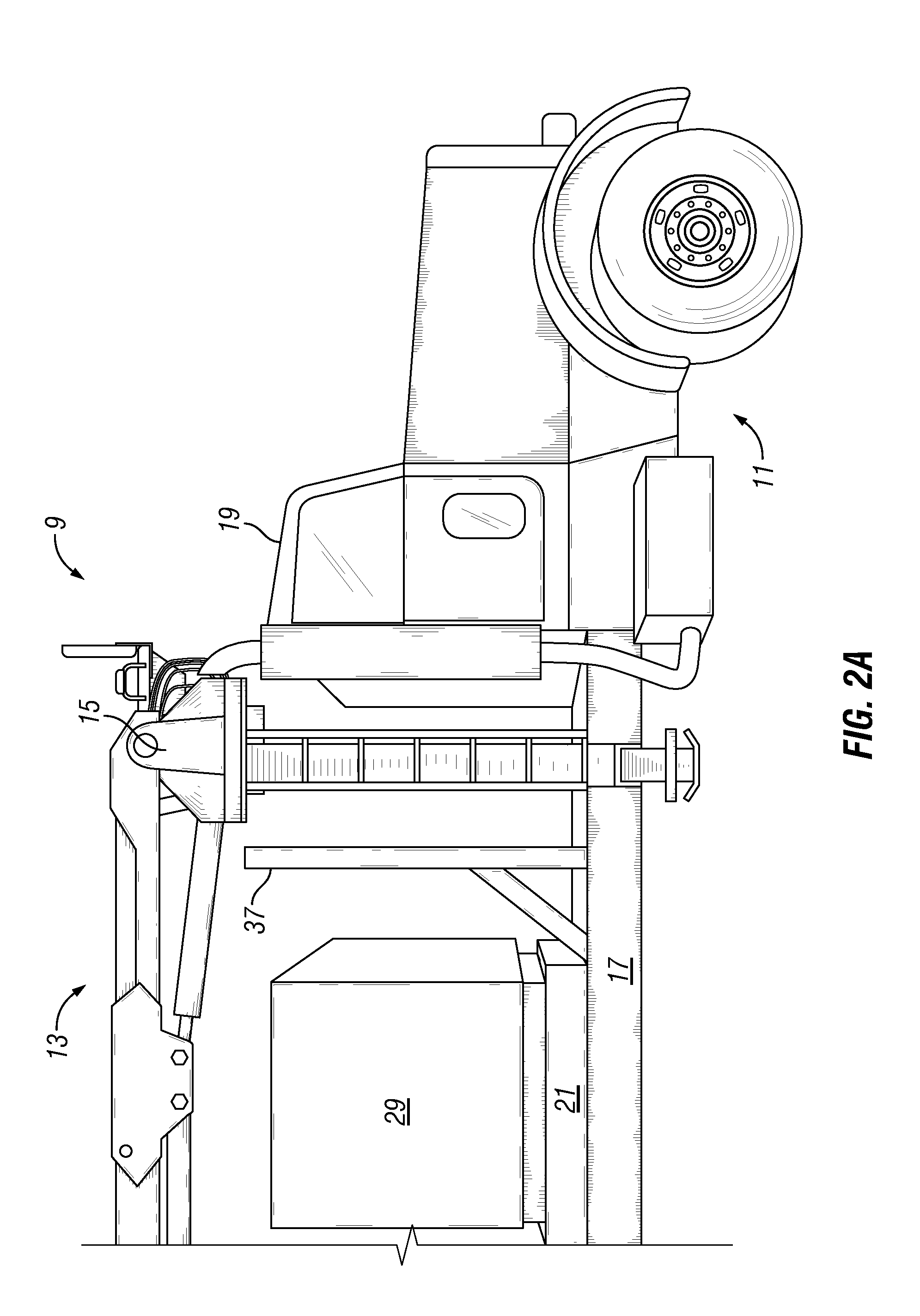
[0021]The present invention now will be described more fully hereinafter with reference to the accompanying drawings in which a preferred embodiment of the invention is shown. This invention may, however, be embodied in many different forms and should not be construed as limited to the embodiment set forth herein. Rather, this embodiment is provided so that this disclosure will be thorough and complete, and will fully convey the scope of the invention to those skilled in the art. Like numbers refer to like elements throughout.
[0022]Referring to FIG. 1, in an embodiment, the mobile solid waste material handling and collection device 9 has a transport vehicle 11 with a waste collection and handling assembly 13 mounted thereon. In this embodiment, the transport vehicle 11 may be a truck that may have three or more axles. The truck may be powered by a diesel engine. Alternatively, the truck may be powered by a gasoline, or other type of engine. An A-frame style knuckleboom loader 15 is ...
PUM
 Abstract
Description
Claims
Application Information