

Pneumatic radial tire for use on passenger cars
- Summary
- Abstract
- Description
- Claims
- Application Information
AI Technical Summary
Benefits of technology
Problems solved by technology
Method used
Image

Examples
working examples
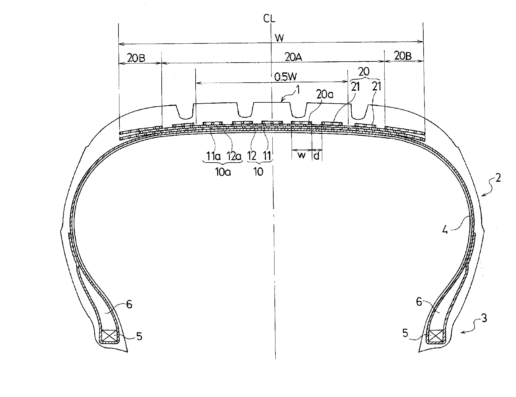
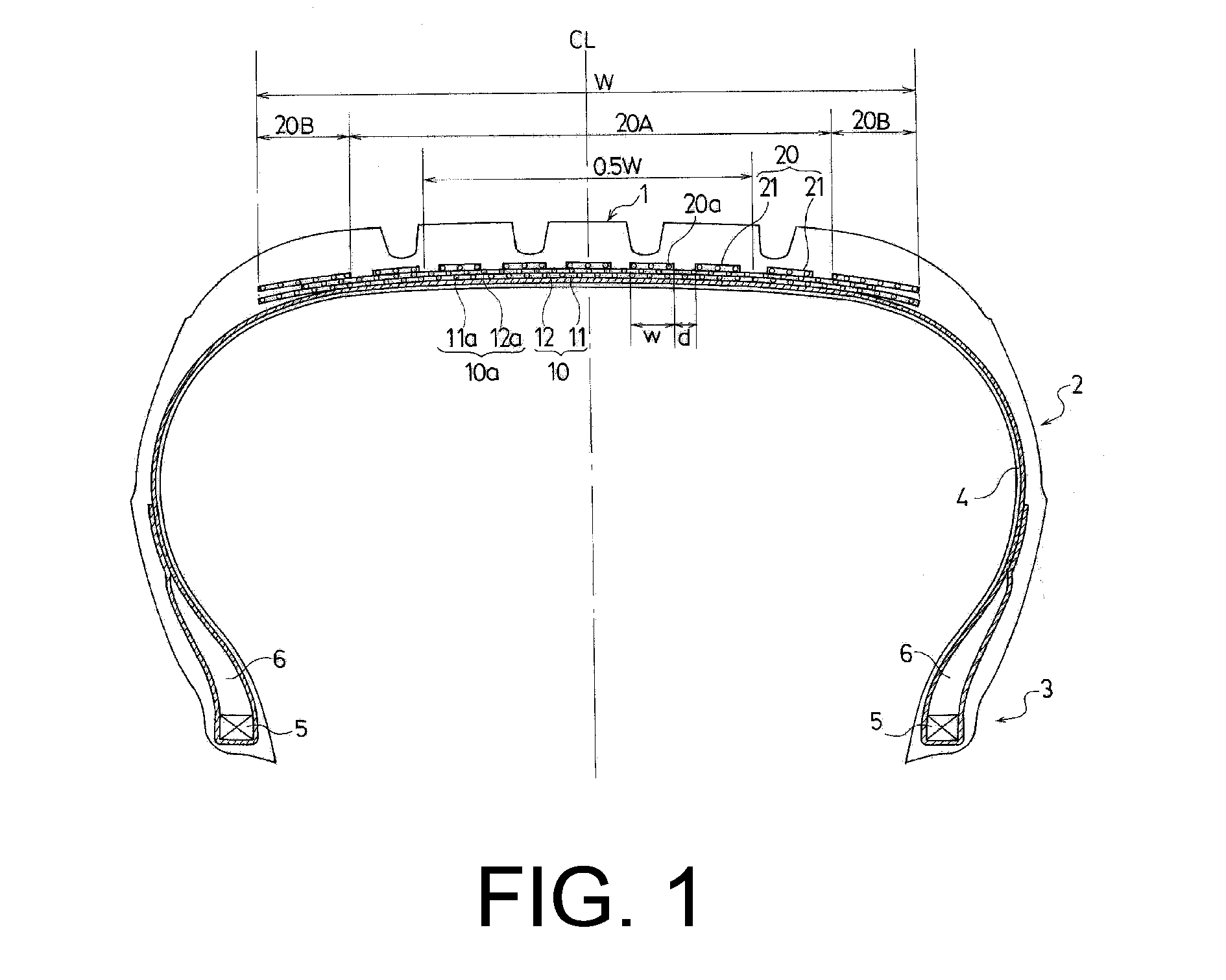
[0040]Eighteen test tires for Comparative Examples 1 to 4 and Working Examples 1 to 14 were fabricated. Each test tire was a pneumatic tire having a tire size of 205 / 55R16 and the fundamental tire structure illustrated in FIG. 1. Each of the form, width with respect to the belt width, sum of widths of contacting or overlapping regions with respect to the width of the belt cover layer, and band-like member winding method for the belt cover layer; inflection point, average elastic modulus, structure, cross-sectional area, cord count, total cross-sectional area, and incline direction with respect to the adjacent belt layer for the steel cords constituting the belt cover layer; and, furthermore, the structure of the belt layer was varied as shown in Tables 1 and 2.
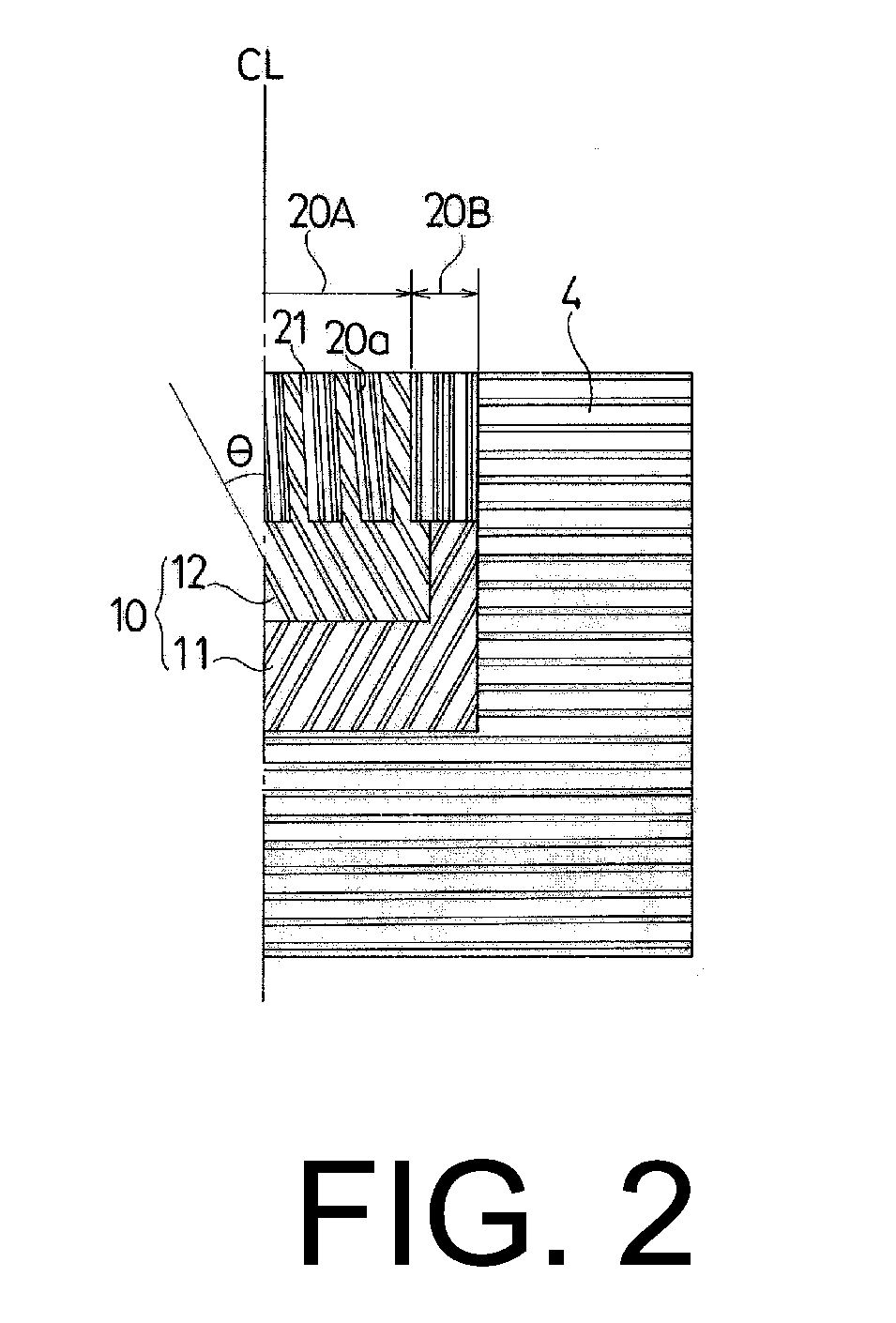
[0041]Note that in the belt layers of each of the 18 types of test tires of Comparative Examples 1 to 4 and Working Examples 1 to 14, the inclination angle of the belt cords with respect to the tire circumferential direction w...
PUM
| Property | Measurement | Unit |
|---|---|---|
| Length | aaaaa | aaaaa |
| Fraction | aaaaa | aaaaa |
| Fraction | aaaaa | aaaaa |
Abstract
Description
Claims
Application Information