Radiation detector, radiation detector fabrication method, and radiographic image capture device

a radiation detector and fabrication method technology, applied in the direction of instruments, x/gamma/cosmic radiation measurement, radiation intensity measurement, etc., can solve the problems of high risk of triggering electrostatic damage, triggering electrostatic damage, and so as to prevent electrostatic damage of photoelectric conversion elements. , the effect of preventing images from becoming more susceptible to blurring

Inactive Publication Date: 2013-02-28
FUJIFILM CORP
View PDF3 Cites 17 Cited by
  • Summary
  • Abstract
  • Description
  • Claims
  • Application Information

AI Technical Summary

Benefits of technology

[0013]In order to address the above issues, an object of the present invention is to provide a radiation detector, a radiation detector fabrication method, and a radiographic image capture device that can prevent electrostatic damage of photoelectric conversion elements, and can also prevent images from becoming more susceptible to blurring.

Problems solved by technology

However, sometimes electrostatic damage of photoelectric conversion elements is triggered by static buildup on the surface of the photoelectric conversion base during surface treatment of the surface of the photoelectric conversion base.
However, there is a high risk of triggering electrostatic damage when plasma processing is performed in a vacuum.
Similar electrostatic damage is also sometimes triggered when static buildup occurs on the surface of the photoelectric conversion base, not only when performing surface treatment.
In order to prevent such electrostatic damage a conduction layer could conceivably be disposed between the scintillator and the photoelectric conversion base, however the thickness of the device would increase and there would be an increase the distance to the photoelectric conversion elements in such cases, making image blurring more likely to occur.

Method used


Image

  • Radiation detector, radiation detector fabrication method, and radiographic image capture device
  • Radiation detector, radiation detector fabrication method, and radiographic image capture device
  • Radiation detector, radiation detector fabrication method, and radiographic image capture device

Examples


Embodiment Construction

[0031]Explanation follows regarding examples of exemplary embodiments, with reference to the drawings.

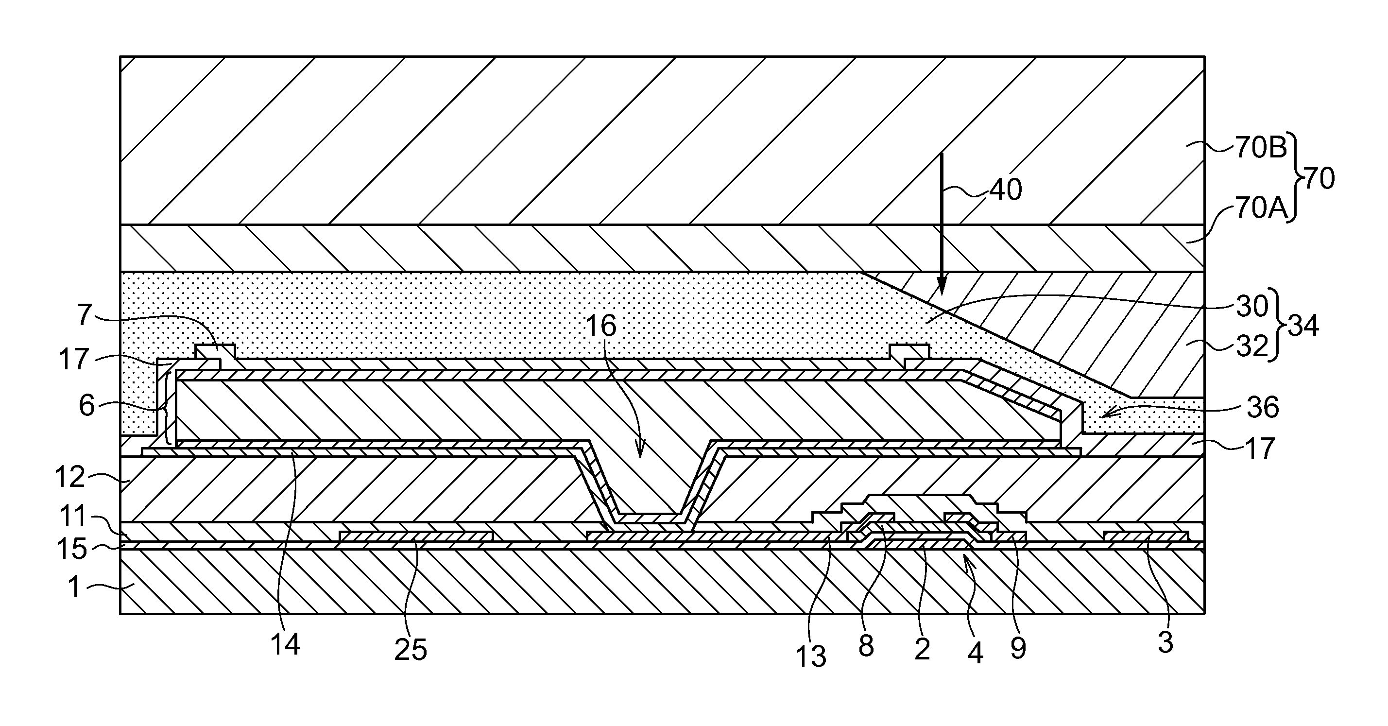
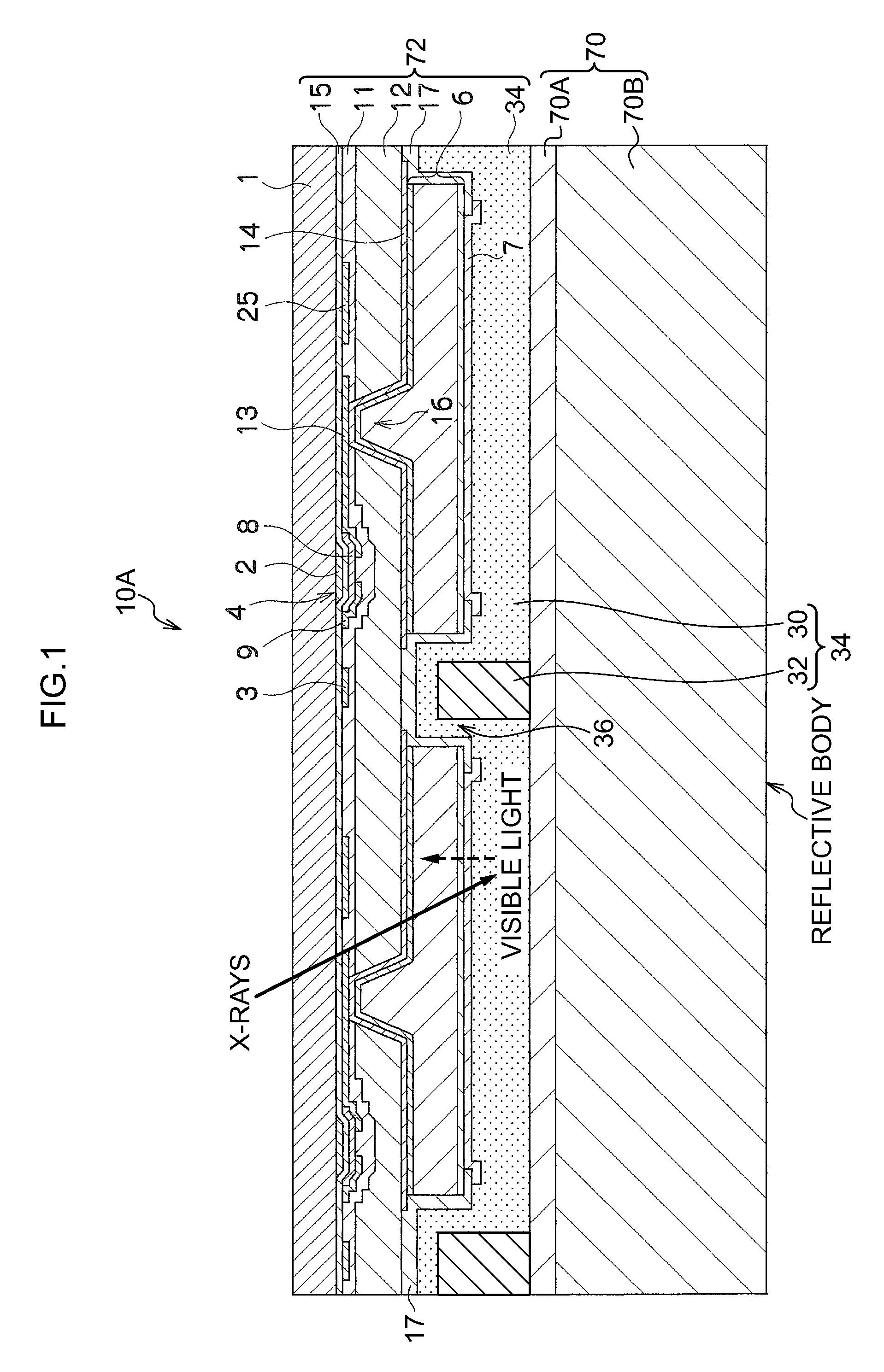
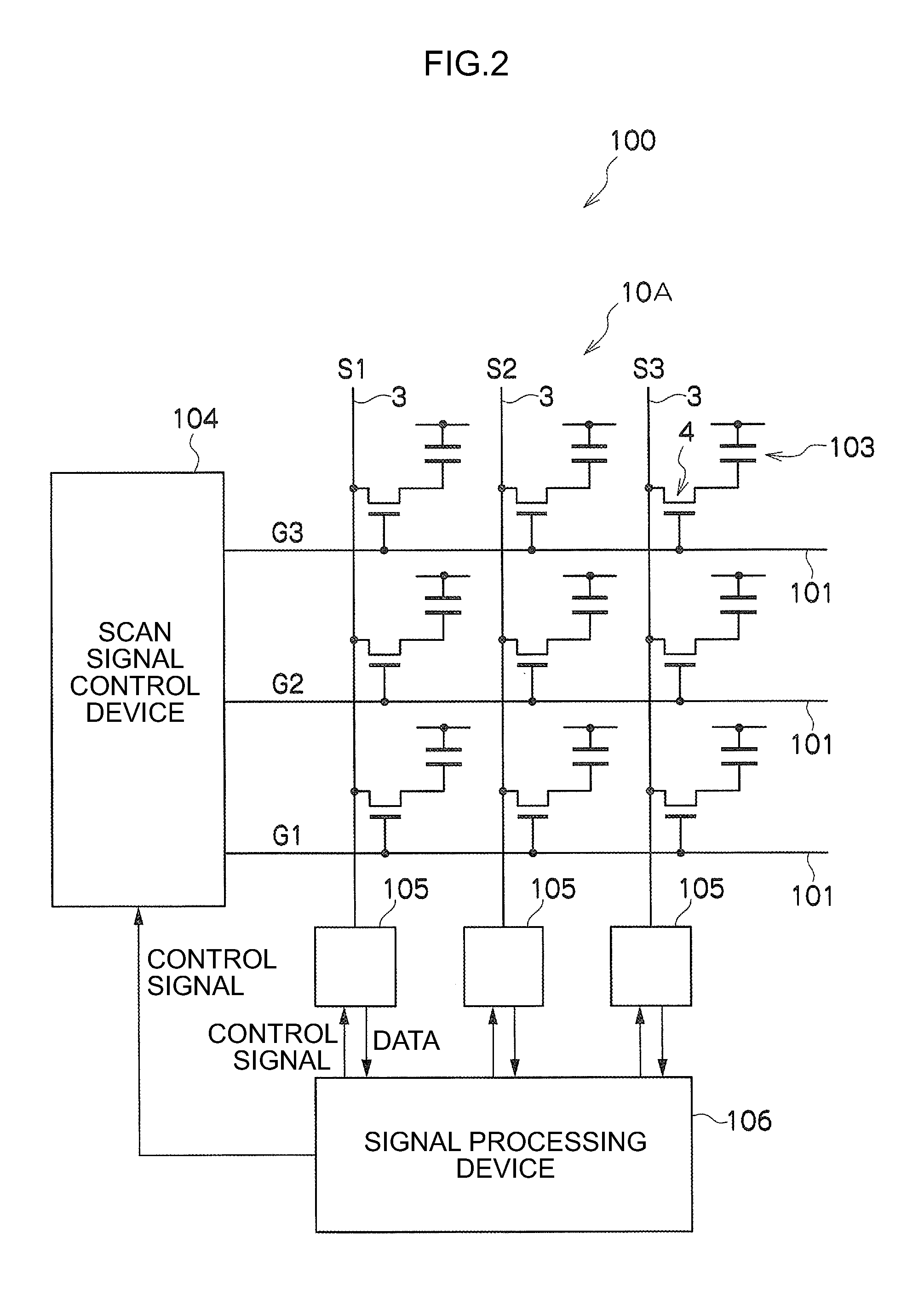
[0032]FIG. 1 and FIG. 2 illustrate the overall configuration of a radiographic image capture device 100 employing a radiation detector 10A according to a first exemplary embodiment. Note that a scintillator 70 has been omitted in FIG. 2.

[0033]The radiographic image capture device 100 of the present exemplary embodiment is equipped with the indirect conversion method radiation detector 10A.

[0034]The radiation detector 10A is provided with the scintillator 70 serving as a light emitting layer, and a photosensor-equipped TFT array substrate 72 serving as a photoelectric conversion base.

[0035]Explanation follows first regarding the scintillator 70. The scintillator 70 converts irradiated radiation into light and emits the converted light. A reflective body is provided at the bottom portion of the scintillator 70 illustrated in FIG. 1 to reflect light.

[0036]Explanation follows regarding ...


PUM


Abstract

A radiation detector is provided that includes: plural pixels, each provided with a sensor portion including a switching element formed on a substrate and a photoelectric conversion element that is formed on the substrate and generates charge according to illuminated light; a planarizing layer formed on the plural pixels and including a light-blocking member with antistatic properties formed in a portion of the planarizing layer; and a light emitting layer that is formed on the planarizing layer and emits light according to irradiated radiation.

Description

CROSS-REFERENCE TO RELATED APPLICATION[0001]This application claims priority under 35 USC 119 from Japanese Patent Application No. 2011-185061, filed on Aug. 26, 2011, the disclosure of which is incorporated by reference herein.BACKGROUND[0002]1. Technical Field[0003]The present invention relates to a radiation detector, a radiation detector fabrication method, and a radiographic image capture device.[0004]2. Related Art[0005]Radiographic image capture devices for capturing radiographic images are known in which a radiation detector detects radiation that has been irradiated from a radiation irradiation device and has passed through a subject. As the radiation detector for such a radiographic image capture device, detectors are known that are provided with a scintillator such as a fluorescent body that converts irradiated radiation into light, and a photoelectric conversion base configured from pixels. Each pixel is provided with a photoelectric conversion element that generates cha...

Claims


Application Information

Patent Timeline
Patent Type & Authority Applications(United States)
IPC IPC(8): G01T1/20H01L31/18G01T1/202
CPCH01L27/14692H01L27/14663
Inventor OHTA, YASUNORISATO, KEIICHIRONISHINO, NAOYUKINAKATSUGAWA, HARUYASU
Owner FUJIFILM CORP
Why Eureka
Try Eureka