Driver Circuit for Efficiently Driving a Large Number of LEDs

Active Publication Date: 2013-02-28
INFINEON TECH AG
View PDF3 Cites 44 Cited by
  • Summary
  • Abstract
  • Description
  • Claims
  • Application Information

AI Technical Summary

Benefits of technology

The present invention provides a circuit for controlling a plurality of LEDs coupled in series (LED chain). The circuit includes a switching converter that provides a constant load current to the LEDs, and a floating driver circuit that controls the intensity of light emitted by the LEDs. The floating driver circuit is coupled in parallel to each individual LED and includes a bypass transistor and a diode to limit the voltage across the load current path. The circuit also includes a logic gate that can override the modulated signal in case of an over-voltage signal. The technical effects of the present invention are a more efficient and precise control of LEDs, reduced power consumption, and improved stability and reliability.

Problems solved by technology

However, the brightness of the LEDs cannot be individually controlled which is particularly desirable when using LEDs of different colors for additive mixing of colors.
However, known approaches may not enable a brightness control for each individual LED, undesired current mismatch between LEDs may occur due to tolerances, and often a number of bulky inductors may be required.

Method used


Image

  • Driver Circuit for Efficiently Driving a Large Number of LEDs
  • Driver Circuit for Efficiently Driving a Large Number of LEDs
  • Driver Circuit for Efficiently Driving a Large Number of LEDs

Examples


Embodiment Construction

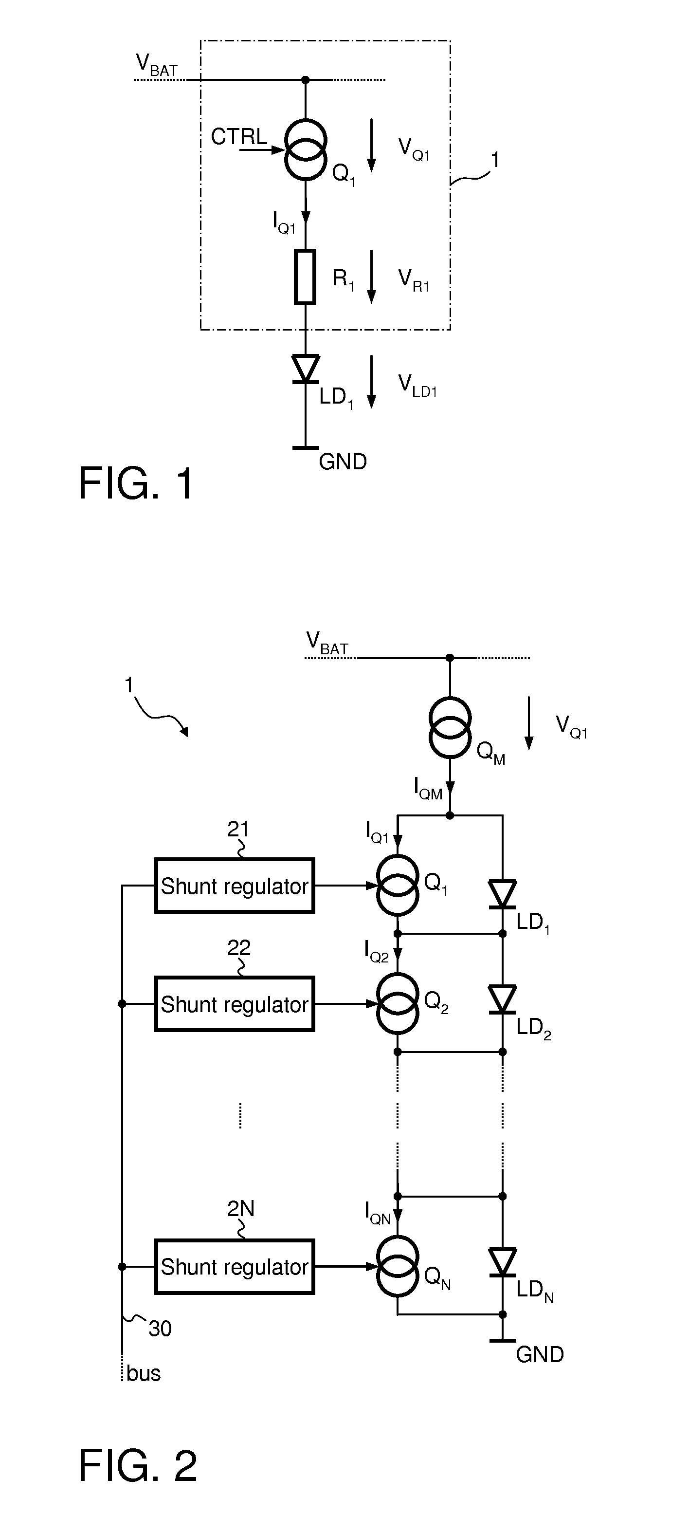
[0019]FIG. 1 illustrates a commonly used driver circuit 1 for driving a light emitting diode LD1. The driver circuit 1 comprises a current source Q1 and an optional series resistor R1 both connected in series to the light emitting diode LD1. In the present example, the current source Q1 is supplied from a first supply potential VBAT that is provided, for example, by an automotive battery. The cathode of the light emitting diode LD1 is connected to a reference supply terminal providing a reference supply potential, e.g., ground potential GND. However, the positions of the diode LD1, the optional resistor R1, and the current source Q1 may be interchanged arbitrarily.

[0020]In order to adjust the brightness of the light emitting diode LD1, the current source Q1 may be controllable, that is, the load current IQ1 passing through the current source Q1 is dependent on a control signal CTRL received by the current source Q1.

[0021]The power losses PD dissipated in the driver circuit may be ca...


PUM


Abstract

A circuit can be used for controlling a plurality of LEDs coupled in series. A switching converter operates as a current source coupled to the plurality of LEDs to provide a constant load current thereto. The switching converter includes an inductor coupled in series with the plurality of LEDs such that the same load current flows through the inductor and the plurality of LEDs. No substantial capacitance is coupled between the inductor and the plurality of LEDs. A floating driver circuit is coupled in parallel with each individual LED of the plurality of LEDs. The floating driver circuit is configured to fully or partially take over the load current thereby bypassing the respective LED in accordance with a respective modulated input signal to control the intensity of the light emitted by the LED.

Description

TECHNICAL FIELD[0001]The invention relates to the field of driver circuits for light emitting diodes (LEDs), especially for a large number of LEDs which are employed, e.g., in flat panel display devices.BACKGROUND[0002]Light emitting diodes (LEDs) are increasingly utilized for illumination and display applications since high power LEDs are available at low costs. In order to provide a constant light intensity light emitting diodes have to be driven with a constant load current.[0003]For driving a single LED or a plurality of LEDs with a constant current special driver circuits have been developed. When driving a very large number of LEDs, such as LED matrices employed in LED display devices efficiency becomes a major issue as well as a precise load current setting in order to ensure a homogeneous emission of light throughout the matrix. Connecting several LEDs in series may reduce the power dissipation in the driver circuits. However, the brightness of the LEDs cannot be individuall...

Claims


Application Information

Patent Timeline
IPC IPC(8): H05B37/02H05B44/00
CPCH05B33/083H05B33/089H05B33/0815H05B33/0851H05B45/48H05B45/10H05B45/37H05B45/54H05B47/24Y02B20/30
Inventor LOGIUDICE, ANDREA
Owner INFINEON TECH AG
Why Eureka
Try Eureka