Printing fluid cartridge, printing apparatus, and use of printing fluid cartridge

a technology of printing fluid and cartridge, which is applied in the direction of printing, etc., can solve the problems of reducing the likelihood of unstable electrical connection between the electrical interface of the ink cartridge and the and reducing the likelihood of unstable electrical connection between the at least one electrical interface and the at least one contact of the cartridge mounting portion

Active Publication Date: 2013-02-28
BROTHER KOGYO KK
View PDF1 Cites 50 Cited by
  • Summary
  • Abstract
  • Description
  • Claims
  • Application Information

AI Technical Summary

Benefits of technology

[0008]Therefore, a need has arisen for a printing fluid cartridge and a printing apparatus, which overcome these and other shortcomings of the related art. A technical advantage of the present invention is that a likelihood that electrical connection between a printing fluid cartridge and a cartridge mounting portion via an electrical interface becomes unstable is reduced.
[0009]According to an embodiment of the present invention, a printing fluid cartridge comprises a front face oriented toward a first direction, a printing fluid supply portion positioned at the front face, a rear face positioned opposite the front face and oriented toward a second direction opposite the first direction, at least one electrical interface positioned between the front face and the rear face, and an engagement surface facing in the second direction. The at least one electrical interface is offset from the printing supply portion with respect to a third direction perpendicular to the first direction and the second direction. The at least one electrical interface is positioned closer to the front face than the engagement surface is, and the at least one electrical interface and the engagement surface intersect a plane which is parallel with the first direction, the second direction, and the third direction.
[0010]With this configuration, an engagement member of an cartridge mounting portion slides on the at least one electrical interface during insertion of the printing fluid cartridge into the cartridge mounting portion. Therefore dust on the at least one electrical interface may be wiped off and a likelihood that electrical connection between the at least one electrical interface and at least one contact of the cartridge mounting portion becomes unstable is reduced.

Problems solved by technology

When dust adheres to the electrical interfaces, the electrical connection between the electrical interfaces of the ink cartridge and the contacts of the cartridge mounting portion may become unstable, such that the date fails to be read out from the semiconductor memory.
Therefore dust on the at least one electrical interface may be wiped off and a likelihood that electrical connection between the at least one electrical interface and at least one contact of the cartridge mounting portion becomes unstable is reduced.

Method used


Image

  • Printing fluid cartridge, printing apparatus, and use of printing fluid cartridge
  • Printing fluid cartridge, printing apparatus, and use of printing fluid cartridge
  • Printing fluid cartridge, printing apparatus, and use of printing fluid cartridge

Examples


Embodiment Construction

[0026]Embodiments of the present invention, and their features and advantages, may be understood by referring to FIGS. 1-11B, like numerals being used for like corresponding parts in the various drawings.

[Printer 10]

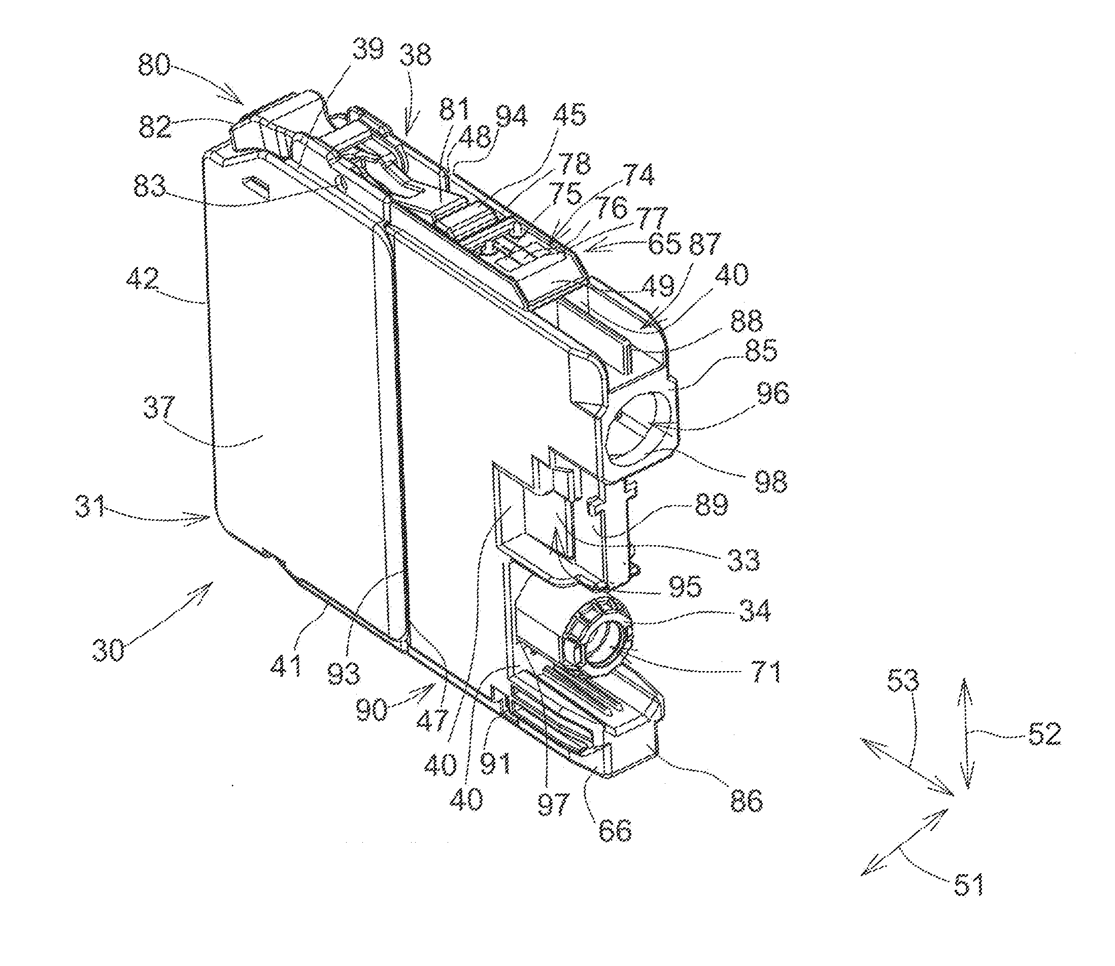
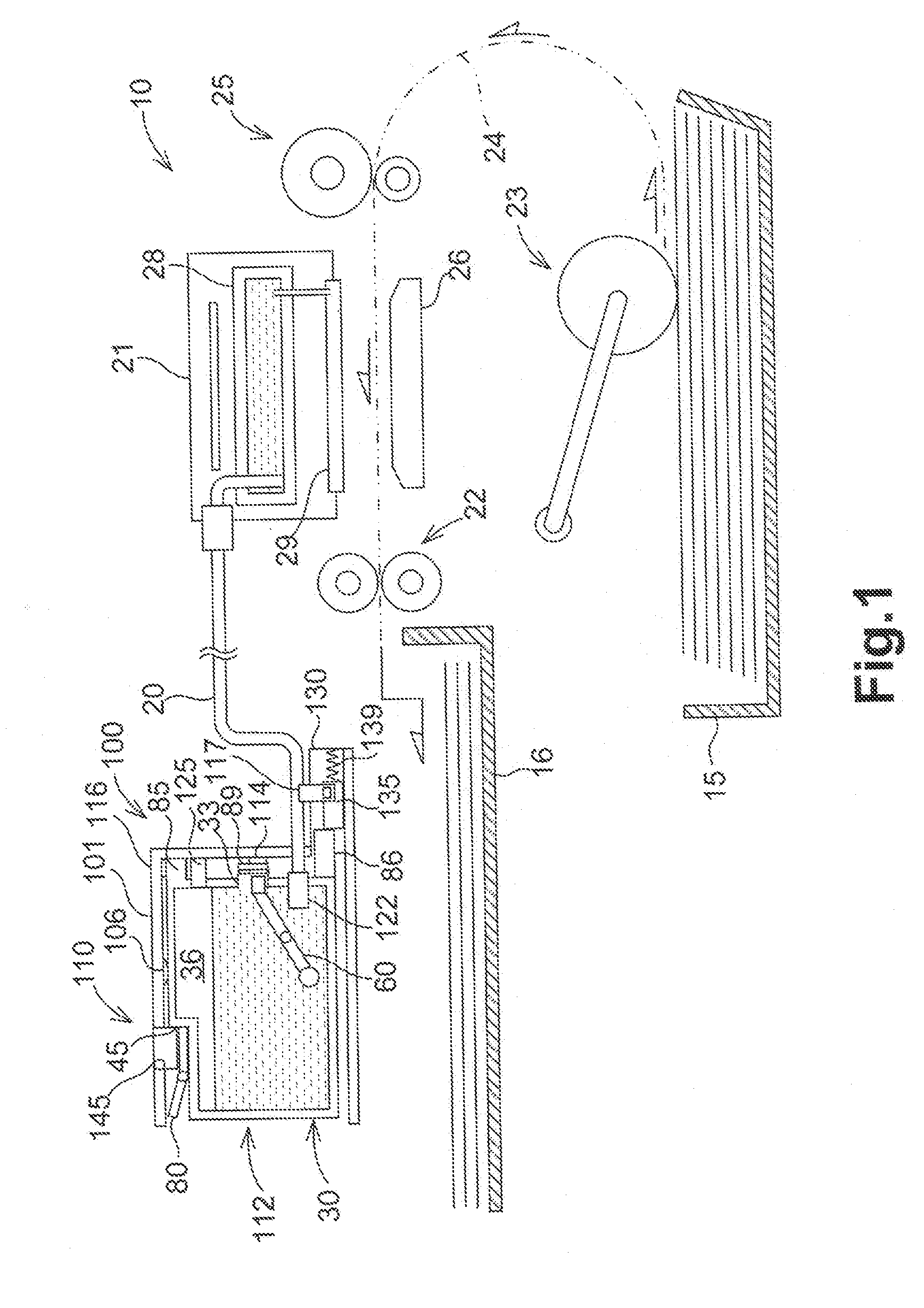
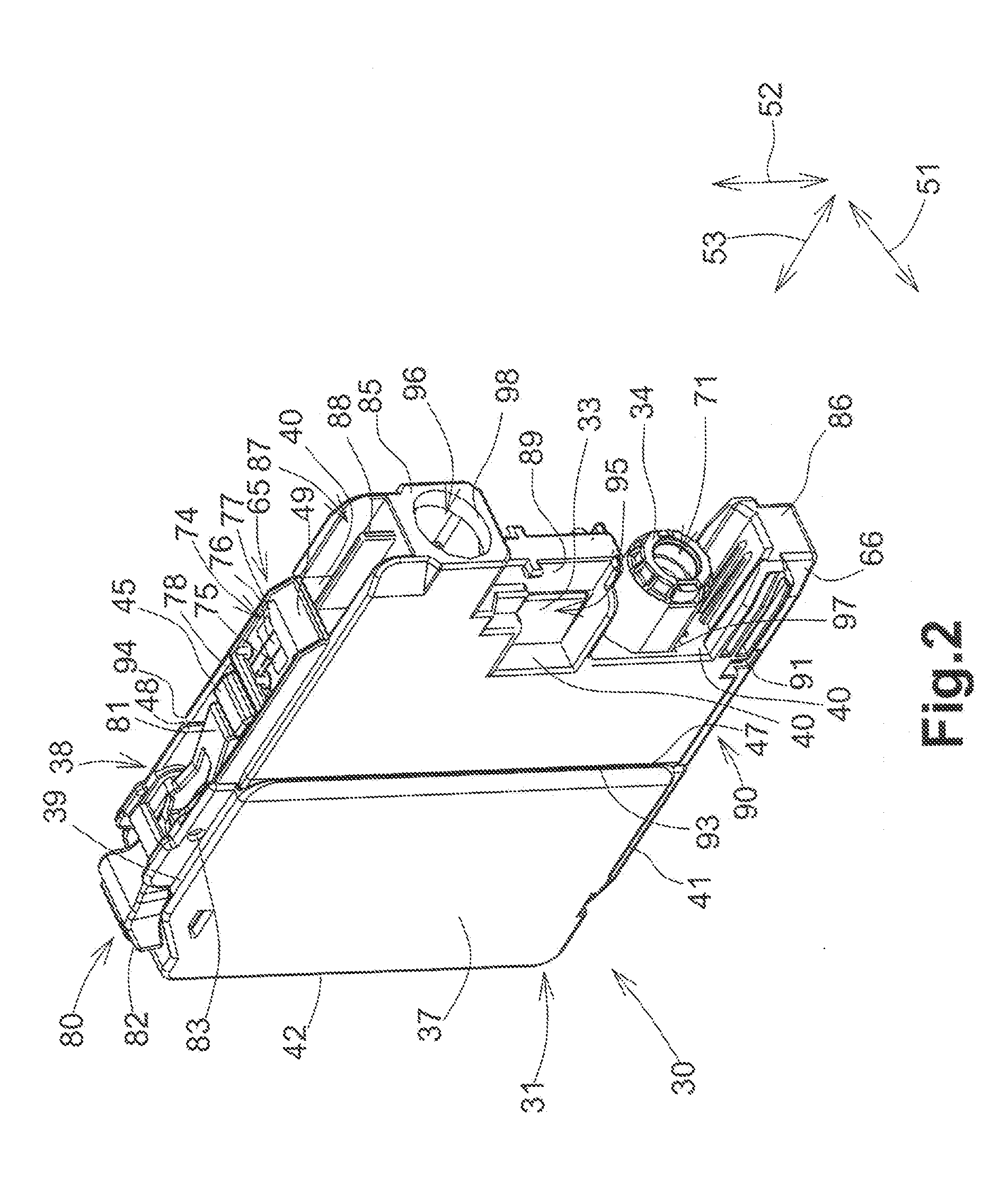
[0027]Referring to FIG. 1, a printing apparatus, e.g., a printer 10 is an inkjet printer configured to print an image on a sheet of printing paper by ejecting ink droplets selectively on the sheet of printing paper. The printer 10 comprises an ink supply device 100. The ink supply device 100 comprises a cartridge mounting portion 110. The cartridge mounting portion 110 is configured to allow a printing fluid cartridge, e.g., an ink cartridge 30 to be mounted therein. The cartridge mounting portion 110 has an opening 112 and the interior of the cartridge mounting portion 110 is exposed to the exterior of the cartridge mounting portion 110 via opening 112. The ink cartridge 30 is configured to be inserted into the cartridge mounting portion 110 via the opening 112, such th...


PUM


Abstract

A printing fluid cartridge includes a front face oriented toward a first direction, a printing fluid supply portion positioned at the front face, a rear face positioned opposite the front face and oriented toward a second direction opposite the first direction, at least one electrical interface positioned between the front face and the rear face, and an engagement surface facing in the second direction. The at least one electrical interface is offset from the printing supply portion with respect to a third direction perpendicular to the first direction and the second direction. The at least one electrical interface is positioned closer to the front face than the engagement surface is, and the at least one electrical interface and the engagement surface intersect a plane which is parallel with the first direction, the second direction, and the third direction.

Description

CROSS REFERENCE TO RELATED APPLICATION[0001]The present application claims priority to and the benefit of Japanese Application No. JP-2011-187779, which was filed on Aug. 30, 2011, the disclosure of which is incorporated herein by reference in its entirety.BACKGROUND OF THE INVENTION[0002]1. Field of the Invention[0003]The present invention relates to a printing fluid cartridge, to a printing apparatus comprising such a printing fluid cartridge, and to use of such a printing fluid cartridge.[0004]2. Description of Related Art[0005]A known image printing apparatus, as described in Patent Application Publication No. JP 2009-132098 A, is configured to print an image on a sheet of printing paper. The known image printing apparatus has an inkjet printing head and is configured to eject ink droplets selectively from nozzles of the printing head onto the sheet of printing paper. The ink droplets land on the sheet of printing paper and thereby a desired image is printed on the sheet of prin...

Claims


Application Information

Patent Timeline
Patent Type & Authority Applications(United States)
IPC IPC(8): B41J2/175
CPCB41J2/175B41J2/17513B41J2/1753B41J2/17553B41J2/17566B41J2/1752B41J2/17526
Inventor KANBE, TOMOHIRONAKAMURA, HIROTAKE
Owner BROTHER KOGYO KK
Why Eureka
Try Eureka