Light emitting unit and liquid crystal display apparatus having the same

Active Publication Date: 2013-02-28
SAMSUNG ELECTRONICS CO LTD
View PDF7 Cites 39 Cited by
  • Summary
  • Abstract
  • Description
  • Claims
  • Application Information

AI Technical Summary

Benefits of technology

The patent text describes a light emitting unit that prevents degradation of its fluorescent member caused by heat. The fluorescent member is mounted in a container separate from the LED chip that generates heat. This prevents the property of the fluorescent member from being compromised and allows it to perform its duties for a long time. Overall, this results in improved performance and longer lifespan of the light emitting unit.

Problems solved by technology

When the fluorescent member has a poor thermal property, the lifespan is reduced due to the heat dissipated from the light source.
In particular, the heat dissipated from the light source is becoming an important issue in a quantum dot which receives attention as the fluorescent member in recent years.
However, it is understood that one or more exemplary embodiment are not required to overcome the disadvantages described above, and may not overcome any of the problems described above.

Method used


Image

  • Light emitting unit and liquid crystal display apparatus having the same
  • Light emitting unit and liquid crystal display apparatus having the same
  • Light emitting unit and liquid crystal display apparatus having the same

Examples


second embodiment

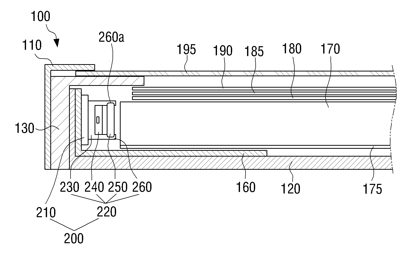
[0066]The light emitting unit will be described below.

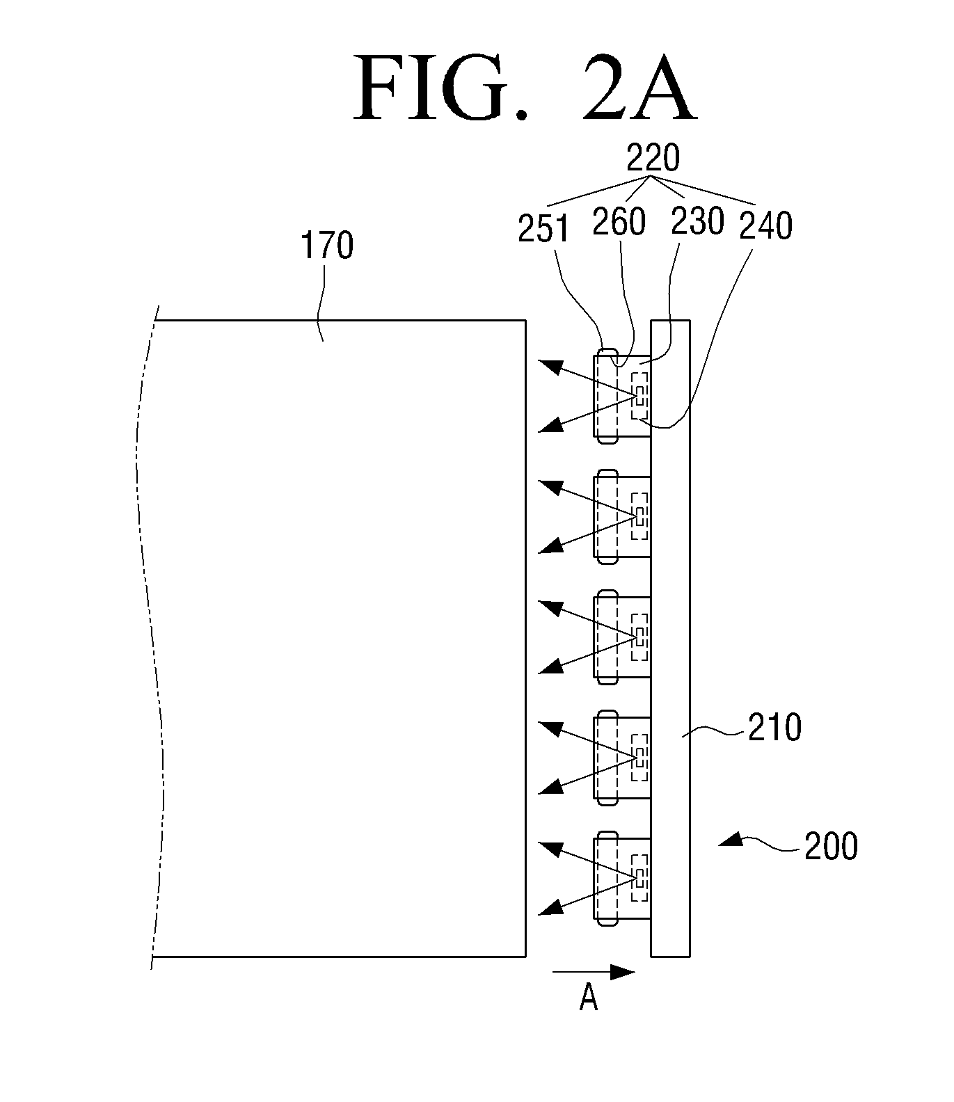
[0067]Referring to FIG. 2B, the light emitting unit 200 according to the second exemplary embodiment includes fluorescent members 252. The number of the fluorescent member 252 is at least one less than the number of the light sources 240. In the exemplary embodiment, five light sources 240 and two fluorescent members 252 are provided. The number of the light source 240 and the number of the fluorescent members 252 are only illustrative, as long as the number of the fluorescent members 252 is less than the number of the light sources 240.

[0068]From FIG. 2B, a fluorescent member 252 disposed in an upper side is mounted in three fluorescent member mount units 260 and a fluorescent member disposed in a lower side is mounted in two fluorescent member mount units 260. Thus, the one fluorescent member 252 spans across three light source units 220, and the other fluorescent member 252 spans across two light source units 220.

[0069]In the...

fifth embodiment

[0081]The light emitting unit will be reviewed below.

[0082]Referring to FIG. 4B, like the light emitting unit 200 of the second embodiment, the light emitting unit 200 includes fluorescent members 257. The number of the fluorescent members 257 is at least one less than the number of the light sources 240. In the exemplary embodiment, five light sources 240 and two fluorescent members 257 are provided. The number of the light sources 240 and the number of the fluorescent material members 257 are only illustrative, as long as the number of the fluorescent members 257 is less than the number of the light sources 240.

[0083]From FIG. 4B, a fluorescent member 257 disposed at a left side is mounted a three fluorescent member mount units 260 and a fluorescent member 257 disposed at a right side is mounted in two fluorescent member mount units 260. Thus, the one fluorescent member 257 spans across three light source units 220, and the other fluorescent member 257 spans across two light sour...

third embodiment

[0086]Referring to FIG. 4C, in the light emitting unit 200 according to the sixth exemplary embodiment, like the third embodiment, one fluorescent member 258 is mounted in fluorescent member mount units 260 each of which is included in each of the plurality of the container member 230, along a length direction of the driving board 210. Thus, the fluorescent member 258 spans across all the light source units 220 aligned in the length direction.

[0087]In the light emitting unit 200 of the sixth exemplary embodiment, only one fluorescent member 258 is mounted like the third exemplary embodiment and thus fabrication and mounting of the fluorescent member 258 is facilitated.

[0088]FIG. 5 is a schematic cross-sectional view illustrating an LCD apparatus according to an exemplary embodiment.

[0089]The LCD apparatus 1 of FIG. 5 illustrates an LCD television (TV). However, it should be understood by those skilled in the art that the LCD apparatus according to an exemplary embodiment may be appl...


PUM


Abstract

A light emitting unit and a liquid crystal display apparatus including the same are provided. The light emitting unit includes a light source unit which generates light, and a driving board which drives the light source unit. The light source unit includes a light source which generates the light, a container member which forms an opening therein and which contains the light source within the opening, and a fluorescent member mounted in the opening of the container member. The light source and the florescent member are spaced apart.

Description

CROSS-REFERENCE TO RELATED APPLICATION[0001]This application claims priority from Korean Patent Application No. 10-2011-0087175, filed on Aug. 30, 2011, in the Korean Intellectual Property Office, the disclosure of which is incorporated herein by reference in its entirety.BACKGROUND[0002]1. Field[0003]Apparatuses consistent with exemplary embodiments relate to a light emitting unit for a liquid crystal display (LCD) apparatus and an LCD apparatus having the same.[0004]2. Description of the Related Art[0005]LCD apparatuses are an apparatus for implementing an image using liquid crystal (LC). The LCD apparatuses are applied to various types of display apparatuses such as a television or a computer monitor.[0006]The LCD apparatus includes an LC panel which display light into an image and a light emitting unit which provides the light to the LC panel.[0007]Typically, an exterior electrode fluorescent lamp (EEFL), a cold cathode fluorescent lamp (CCFL), or the like has been used as the l...

Claims


Application Information

Patent Timeline
IPC IPC(8): G02F1/13357F21V8/00
CPCG02F1/133603G02F1/1335
Inventor SEO, JEONG-PHILHUR, GIL-TAEKWON, YONG-HUNLEE, KYE-HOONLEE, YOUNG-MINCHO, KUN-HOCHOI, SUK-JU
Owner SAMSUNG ELECTRONICS CO LTD
Why Eureka
Try Eureka