
Lighting unit and methods

a technology of light source and light source, applied in the field of light source unit and method, can solve the problems of high operating voltage, large amount of power consumption, poor color quality, etc., and achieve the effects of enhancing flexibility in tailoring, simple procedure, and minimal cos

Inactive Publication Date: 2013-02-28
NEXT LIGHTING CORP
View PDF12 Cites 63 Cited by
  • Summary
  • Abstract
  • Description
  • Claims
  • Application Information

AI Technical Summary

Benefits of technology

The invention is a new lighting unit with many advantages over previous designs. It has features such as energy-saving and smart technologies that can be added without replacing the entire unit. It also allows for easy replacement of the power supply module in case of failure at a significant savings to the end user. Additionally, it provides flexibility in tailoring the lighting unit to meet different user requirements and reduces manufacturing costs by producing a wide range of final products using a single module.

Problems solved by technology

Fluorescent lamps fail under excessive vibration, require a high operating voltage, consume a large amount of power, generally have poor color quality, they cannot be started in cold temperatures or in humid environments, they emit light in 360 degrees about the length of the lamp such that much light is lost in reflection, and they contain mercury, making the lamps difficult to dispose of and hazardous to human health and the environment.
Currently the cost of LED based FTRs is much higher than the fluorescent lamps they replace.
To date, these components have been assembled in a complete module so that failure of one component required replacement of the entire unit.
Typical failures in LED based FTRs occur in the power supply.
The cost of these components and in most cases even the entire power supply is much less than that of the LEDs used in the light module.
Thus the failure of the lowest cost components can trigger an expensive replacement of the entire unit.

Method used


Image

  • Lighting unit and methods
  • Lighting unit and methods
  • Lighting unit and methods

Examples


Embodiment Construction

[0026]The invention provides systems and methods for providing illumination. Various aspects of the invention described herein may be applied to any of the particular applications set forth below or for any other types of lighting units. The invention may be applied as a standalone system or method, or as part of an integrated illumination system. It shall be understood that different aspects of the invention can be appreciated individually, collectively, or in combination with each other.

[0027]Systems

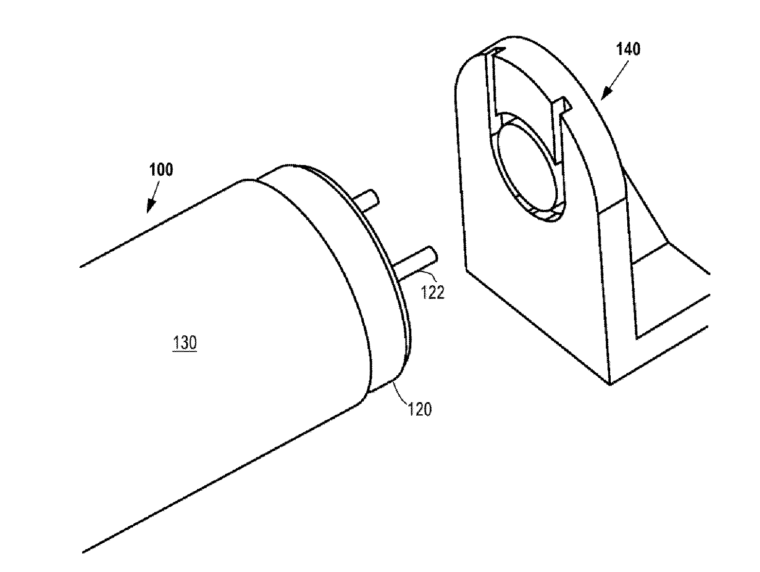
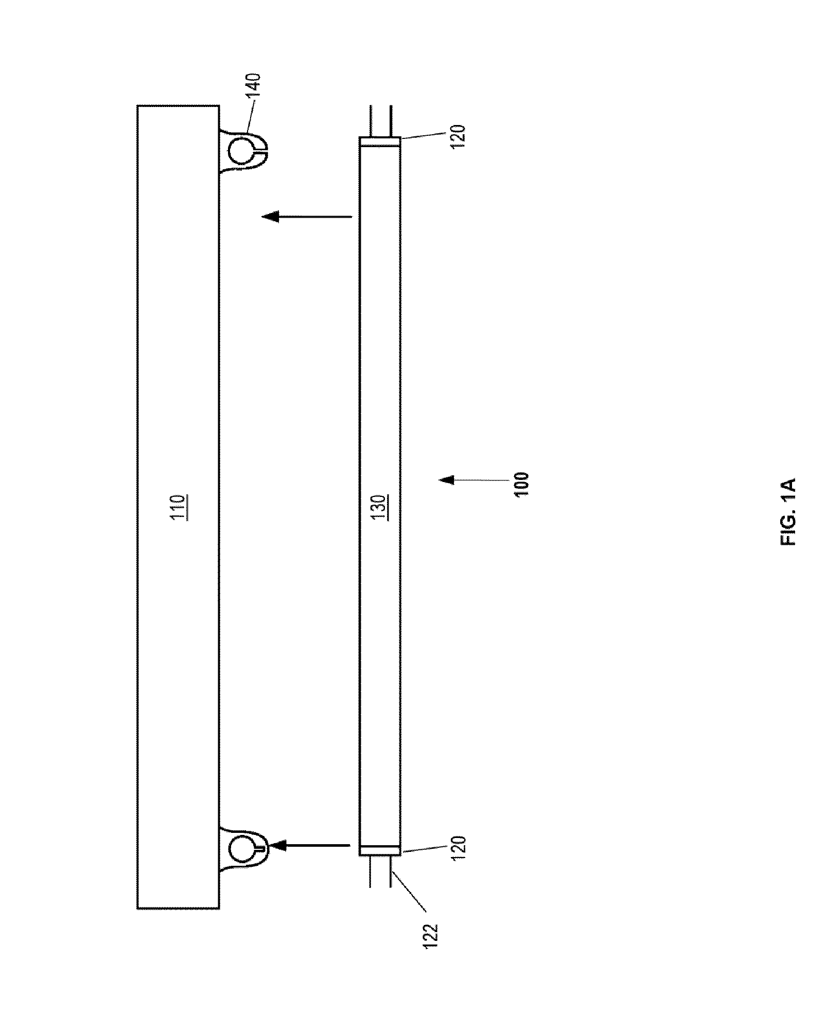
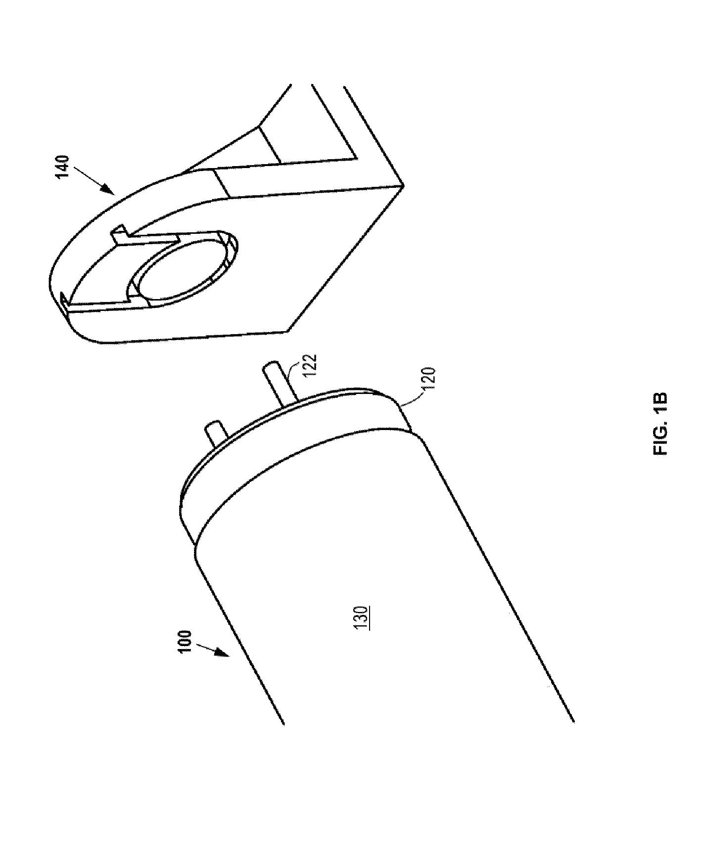
[0028]An aspect of the invention relates to lighting units which may be used for illumination. A lighting unit may provide light suitable for general illumination. A lighting unit may be used as a replacement lamp for conventional lighting fixtures or as a standalone light source. A lighting unit may be used as a replacement for lighting fixtures of various types (e.g., fluorescent lighting fixtures, halogen lighting fixtures, incandescent lighting fixtures, gas discharge lamps, plasma...


PUM

PropertyMeasurementUnit
voltagesaaaaaaaaaa
voltagesaaaaaaaaaa
voltagesaaaaaaaaaa

Abstract

The invention provides systems and methods for providing illumination. A lighting unit, which may be an LED based fluorescent tube replacement, may comprise a power supply and an LED portion produced as separate modules and coupled in a manner that allows the light module and the power supply module to be connected and separated in a reproducible manner. The removable power supply module may enhance the serviceability, customizability and upgradability of the LED based system.

Description

CROSS-REFERENCE[0001]This application claims the benefit of U.S. Provisional Application No. 61 / 528,729, filed Aug. 29, 2011, which application is incorporated herein by reference.BACKGROUND OF INVENTION[0002]Fluorescent lamps are widely used for lighting in commercial buildings, residential spaces, as well as on transit buses and in outdoor lighting. Fluorescent lighting provides some advantages, such as improved efficiency, over other lighting options such as incandescent lighting. However, there are several drawbacks. Fluorescent lamps fail under excessive vibration, require a high operating voltage, consume a large amount of power, generally have poor color quality, they cannot be started in cold temperatures or in humid environments, they emit light in 360 degrees about the length of the lamp such that much light is lost in reflection, and they contain mercury, making the lamps difficult to dispose of and hazardous to human health and the environment. LED based fluorescent tube...

Claims


Application Information

Patent Timeline
Patent Type & Authority Applications(United States)
IPC IPC(8): F21L4/02F21L4/00F21V17/00F21V21/00
CPCF21K9/30F21K9/90F21V17/002F21Y2101/02Y10T29/49716F21S2/005F21V23/06Y10T29/49117F21K9/17F21K9/27F21Y2115/10
Inventor BRETSCHNEIDER, ERICBERKOWITZ, ZACHSOSNICK, RANDALL
Owner NEXT LIGHTING CORP
Learn More