Light Bar and Manufacturing Method Thereof

a manufacturing method and technology of light bars, applied in the field of light bars, can solve the problems of reducing the yield rate, and achieve the effect of high production efficiency and good heat dissipation

Inactive Publication Date: 2013-02-28
BRIVIEW CORPORATION
View PDF0 Cites 4 Cited by
  • Summary
  • Abstract
  • Description
  • Claims
  • Application Information

AI Technical Summary

Benefits of technology

[0007]In view of the problems mentioned above, it is an object of the present invention to provide a manufacturing method of a light bar with high producing efficiency and good heat dispassion.
[0008]It is another object of the present invention to provide the light bar utilizing a metal substrate to improve the heat dissipation effect.
[0009]It is another object of the present invention to provide the light bar utilizing an opening portion to bend the light bar and to elevate the yield rate of the light bar.
[0010]It is another object of the present invention to provide a simplified manufacturing method of the light bar to improve the producing efficiency.
[0014]In comparison to the conventional technology, the light bar and the light bar manufacturing method are utilizing a metal as a substrate to allow the heat from the light sources can dissipating directly through the metal substrate to achieve the purpose of effectively dissipating heat. In addition, the folding line is recessed in the metal substrate to make the metal substrate bent along the folding line to reducing the defective rate of the light bar. Further, by regulating the distance between the opening portion and the electronic component, the fastening portion is prevented from pressing the electronic component while bending the light bar and the producing yield rate can be promoted.

Problems solved by technology

However, the light bar utilizing LED as light source is an electric device still having heat, so it is a major subject to design a better light bar structure and dissipate the heat from the light bar.
However, in the traditional bending process, the bending portion of the light bar 100 is apt to squeeze the connector 600 adjacent to each other so that the connector 600 is easily hurt, causing the yield rate to decrease.

Method used


Image

  • Light Bar and Manufacturing Method Thereof
  • Light Bar and Manufacturing Method Thereof
  • Light Bar and Manufacturing Method Thereof

Examples


Embodiment Construction

[0027]According to one embodiment of the present invention, the light bar is provided for raising the heat dissipating efficiency. In this embodiment, the light bar includes a light emitting diode light bar.

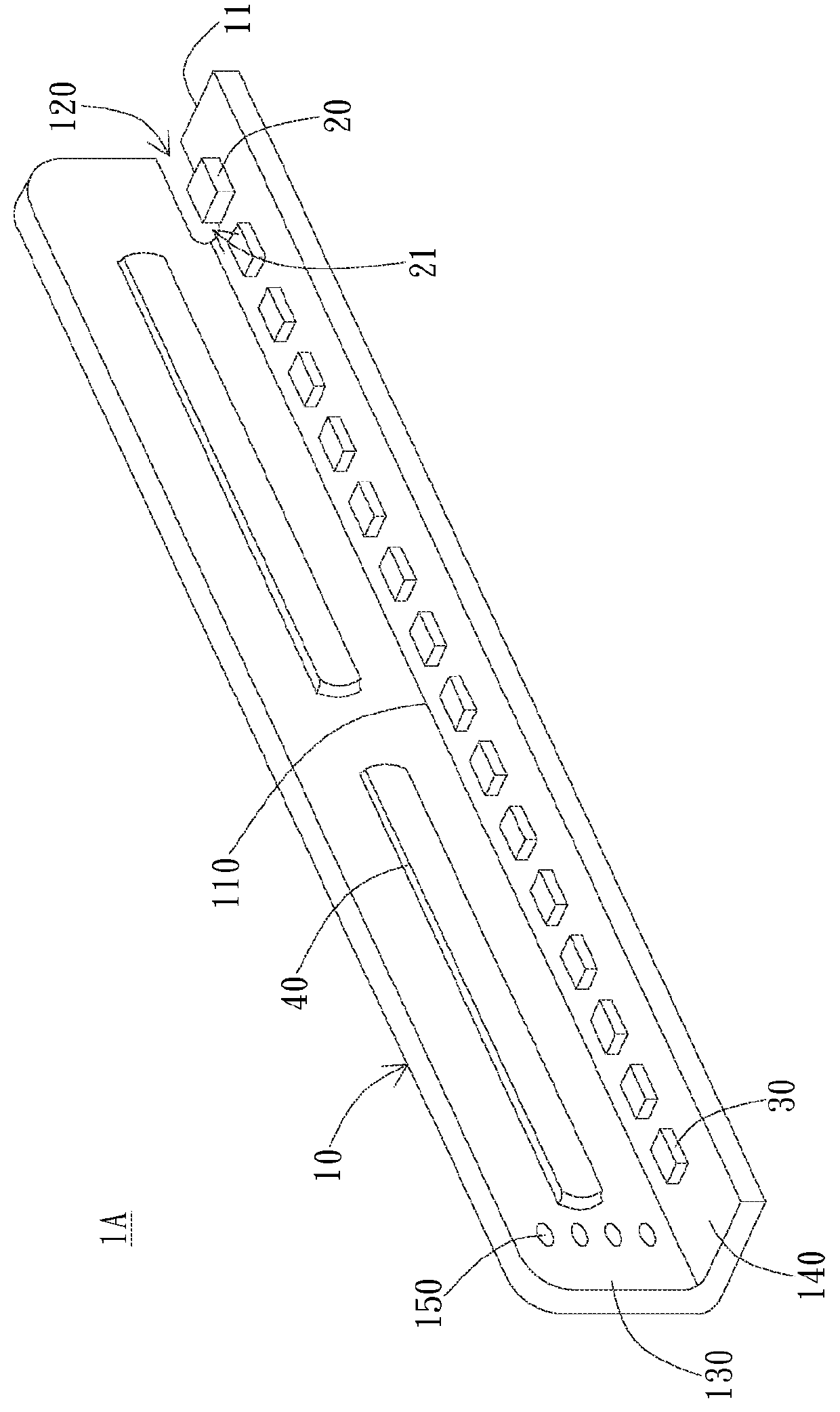
[0028]Please refer to FIG. 2; FIG. 2 shows a schematic view of one embodiment of the light bar. As shown in FIG. 2, the light bar 1A includes a metal substrate 10, an electronic component 20, and a plurality of light sources 30. In this embodiment, the electronic component 20 includes a connector, and the light sources include light emitting diodes. The electronic component 20 connects the light sources 30. In another embodiment, the electronic component 20 may include resistor, capacitor, inductance, electromagnetic shielding component (EMC shielding component) or other components and is not limited to the connector of this embodiment. It is noted that the metal substrate 10 has a folding line 110 and an opening portion 120, wherein the folding line 110 extends along a longer si...


PUM

PropertyMeasurementUnit
distanceaaaaaaaaaa
widthaaaaaaaaaa
widthaaaaaaaaaa

Abstract

A light bar includes a metal substrate, an electronic component, and a plurality of light source. The metal substrate has a folding line and an opening portion, wherein the folding line extends along a longer side of the metal substrate, and the opening portion connects an end of the folding line from a gap of a first edge of the metal substrate. The metal substrate is bent along the folding line, and a fastening portion and a bearing portion are formed on two sides of the folding line, wherein a circuit is formed on the bearing portion, the electronic component is disposed on the bearing portion and connects the circuit, and a gap is formed between the fastening portion and the electronic component. The light sources are disposed on the metal substrate, and the electronic component and the light sources are electrically coupled with the circuit.

Description

BACKGROUND OF THE INVENTION[0001]1. Field of the Invention[0002]The present invention relates to a light bar and the manufacturing method thereof; particularly, the present invention relates to a light bar and the manufacturing method of the light bar which elevate heat dissipation efficiency and simplify the process.[0003]2. Description of the Prior Art[0004]With advances in technology, lighting sources for saving electricity and with more brightness are developed continuously in photoelectric-related industries. For example, Light Emitting Diode (LED) is the most common light source and has advantages such as electricity consumption and less heat producing. LED has substituted for the traditional lighting devices and has been widely employed in various aspect of daily life such as flashlight, desk lamp, monitor displayer, billboard advertisement, and building wall. However, the light bar utilizing LED as light source is an electric device still having heat, so it is a major subjec...

Claims


Application Information

Patent Timeline
Patent Type & Authority Applications(United States)
IPC IPC(8): F21S4/00F21V17/06
CPCF21V17/06Y10T29/49117F21S4/008F21S4/28
Inventor HUANG, TZU-CHIENTSENG, YU-LUNFANG, TING-WEIHUANG, JEN-YANTSAI, PO-FENG
Owner BRIVIEW CORPORATION
Why Eureka
Try Eureka