Image processor, image display apparatus, and image taking apparatus

a technology of image processing and image display, applied in the direction of electrical devices, instruments, computing, etc., can solve the problems of limited depth (projection, depression), stereoscopic viewing impossible, visual fatigue, etc., and achieve the effect of hardly causing fatigue, easy adjustment of three-dimensional effects, and easy enhancement of three-dimensional effects

Inactive Publication Date: 2013-02-28
SHARP KK
View PDF4 Cites 21 Cited by
  • Summary
  • Abstract
  • Description
  • Claims
  • Application Information

AI Technical Summary

Benefits of technology

[0017]It is an object of the present invention to solve the problem and to provide an image processor generating a three-dimensional image easily three-dimensionally viewed by, and hardly causing fatigue of, an observer, and easily adjusting a three-dimensional effect of an arbitrary portion in the three-dimensional image.Means for Solving the Problem

Problems solved by technology

However, if the disparity is increased greater than a certain level, an image sensed by the left eye is not fused with an image sensed by the right eye and a double image appears and makes the stereoscopic viewing impossible (fusional limitation).
A double image due to an excessive disparity is known to cause visual fatigue.
Therefore, to comfortably view a three-dimensional image, a depth (projection, depression) range of an object must be limited when the image is displayed.

Method used


Image

  • Image processor, image display apparatus, and image taking apparatus
  • Image processor, image display apparatus, and image taking apparatus
  • Image processor, image display apparatus, and image taking apparatus

Examples


first embodiment

[0044]The present invention will now be described in detail with reference to the drawings. Configurations in the drawings are exaggeratingly depicted to facilitate understanding and have intervals and sizes different from actual configurations.

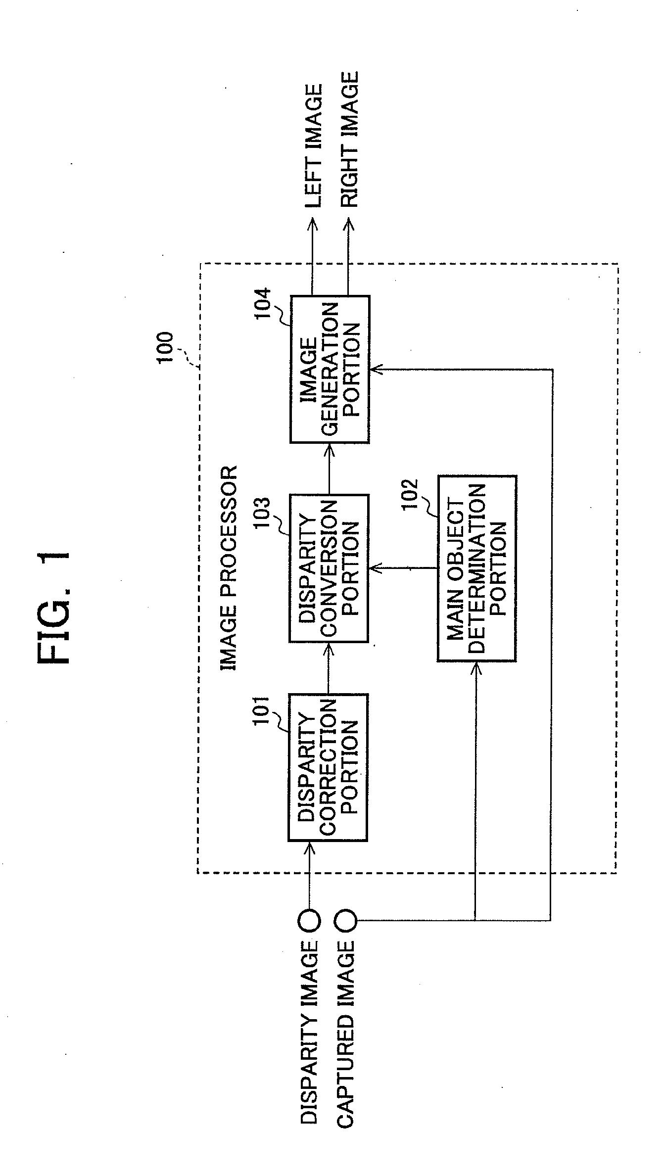
[0045]FIG. 1 is a functional block diagram of an image processor 100 of the present invention described in a first embodiment.

[0046]The image processor 100 is made up of a disparity correction portion 101, a main object determination portion 102, a disparity conversion portion 103, and an image generation portion 104 and uses a captured image from one view point and a disparity image corresponding to the captured image as inputs to generate a three-dimensional image based on the captured image and the disparity image.

[0047]A disparity image input from an external device (not depicted) etc., is input to the disparity correction portion 101. A captured image input from an external device etc., is input to the main object determination portion 1...

second embodiment

[0112]A second embodiment of the present invention will hereinafter be described in detail with reference to the drawings. However, the portions having the same functions as the first embodiment are denoted by the same reference numerals.

[0113]FIG. 11 is a functional block diagram of an image processor 1100 of the present invention described in the second embodiment.

[0114]The image processor 1100 is formed by adding a disparity calculation portion 1101 to the image processor 100 described with reference to FIG. 1 and uses two captured images acquired by shooting an identical object from two viewing positions as inputs to generate a three-dimensional image based on the captured images.

[0115]The two captured images acquired by shooting an identical object from at least two viewing positions are input to the disparity calculation portion 1101. Any one of the two captured images is input to the main object determination portion 102 and the image generation portion 104. One captured imag...

third embodiment

[0129]A third embodiment of the present invention will hereinafter be described in detail with reference to the drawings. However, the portions having the same functions as the first embodiment are denoted by the same reference numerals.

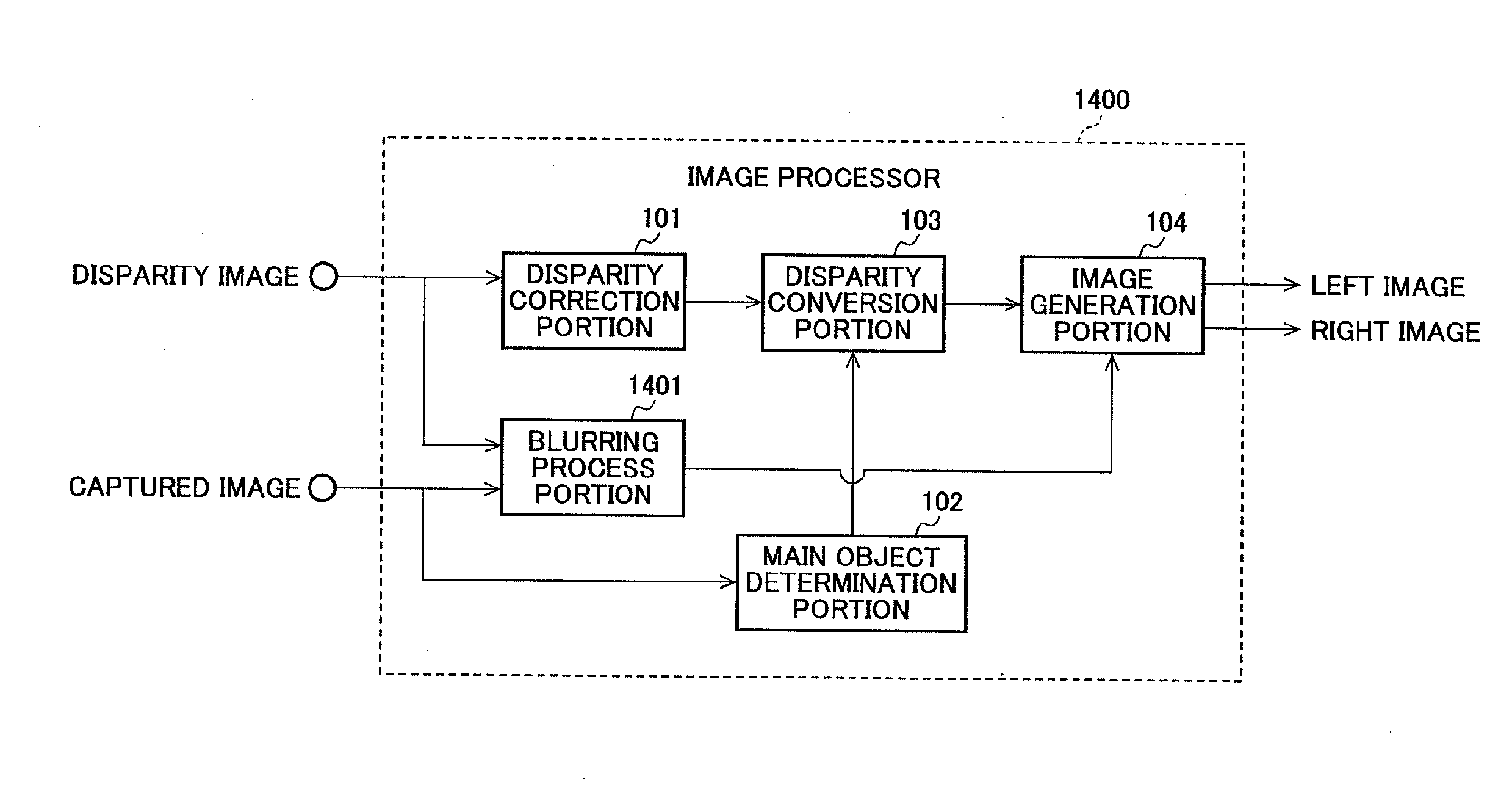
[0130]FIG. 14 is a functional block diagram of an image processor 1400 of the present invention described in the third embodiment.

[0131]The image processor 1400 of FIG. 14 is formed by adding a blurring process portion 1401 to the image processor 100 described with reference to FIG. 1.

[0132]A disparity image input from an external apparatus etc., is input to the disparity correction portion 101 and the blurring process portion 1401. A captured image input from an external apparatus etc., is input to the main object determination portion 102 and the blurring process portion 1401.

[0133]The blurring process portion 1401 executes a blurring process for a pixel value of the captured image corresponding to an object having a disparity equal to or less than...


PUM


Abstract

Disclosed is an image processor generating a three-dimensional image easily three-dimensionally viewed by, and hardly causing fatigue of, an observer, and easily adjusting a three-dimensional effect of an arbitrary portion in the three-dimensional image. The disparity correction portion 101 corrects a disparity of the input disparity image within a predetermined range and outputs a disparity image storing the corrected disparity to the disparity conversion portion 103. The disparity conversion portion 103 converts the disparity of the disparity image such that a disparity corresponding to the image of the main object determined by the main object determination portion 102 reaches a predetermined value, and outputs the disparity image obtained after the conversion to an image generation portion 104. The image generation portion 104 generates an image for the left eye and an image for the right eye based on the input disparity image and the input captured image, and outputs the images to a display apparatus. As a result, the disparity is converted such that the three-dimensional effect of the main object is enhanced.

Description

TECHNICAL FIELD[0001]The present invention relates to an image processor generating a three-dimensional image, an image display apparatus including the image processor, and an image taking apparatus including the image processor.BACKGROUND OF THE INVENTION[0002]A device is proposed that takes images of the same object (hereinafter simply referred to as an identical object) at the same time with two cameras for left and right eyes arranged side-by-side so as to generate a three-dimensional image (also referred to as a stereoscopic image) through the execution of various image processes to two image data (hereinafter, simply referred to as images) generated by the two cameras (see Patent Document 1).[0003]A gap between images generated by overlapping the two images is referred to as a disparity. This disparity varies depending on a distance from cameras to an object.[0004]For example, it is assumed that two cameras are disposed on a straight line with the optical axes of the cameras a...

Claims


Application Information

Patent Timeline
Patent Type & Authority Applications(United States)
IPC IPC(8): G06K9/00G02B30/25H04N13/239
CPCH04N13/0022H04N2013/0081H04N13/0239H04N13/026H04N13/239H04N13/128H04N13/261
Inventor SHIBUHISA, NAOTOKUI, KEI
Owner SHARP KK
Why Eureka
Try Eureka