Optical frequency comb generating device and optical pulse generating device using same, and optical frequency comb generating method and optical pulse generating method using same

a technology of optical frequency comb and generating device, which is applied in the direction of optics, electrical equipment, instruments, etc., can solve the problems of high-cost measuring instrument calibration, inability to accurately calculate input optical power (p/sub>in/sub>), and inability to accurately calculate output optical power, etc., to suppress complication of the overall device, increase cost, and improve accuracy. control

Inactive Publication Date: 2013-02-28
SUMITOMO OSAKA CEMENT CO LTD
View PDF3 Cites 18 Cited by
  • Summary
  • Abstract
  • Description
  • Claims
  • Application Information

AI Technical Summary

Benefits of technology

[0025]According to the first aspect of the invention, the optical frequency comb generating device that has a substrate having an electro-optical effect, a Mach-Zehnder type optical waveguide formed on the substrate, two optical modulation parts independently modulating optical waves propagating in two branch waveguides of the Mach-Zehnder type optical waveguide, and a phase regulator controlling a phase difference between the optical waves propagating in the two branch waveguides and in which a continuous light beam is input to the Mach-Zehnder type optical waveguide, RF signals are supplied to the two optical modulation parts, and an output light beam as an optical frequency comb is output from the Mach-Zehnder type waveguide includes: amplitude adjusting means for adjusting a voltage amplitude of the RF signal supplied to at least one of the optical modulation parts; monitoring means for monitoring intensity of the output light beam; and a bias control circuit that controls the amplitude adjusting means to change a difference in voltage amplitude between the RF signals supplied to each optical modulation part, that detects a variation of the output light beam corresponding to the variation of the difference in voltage amplitude from an output signal of the monitoring means, and that controls the phase regulator on the basis of the detection result to adjust the phase difference. Accordingly, it is not necessary to perform calibration necessary for drive control according to the related art and it is possible to perform more accurate drive control. Since only the variation of the output light beam is monitored, it is possible to suppress complication of the overall device or an increase in cost.
[0026]According to the second aspect of the invention, since the optical pulse generating device includes: the optical frequency comb generating device according to the first aspect; and a dispersion compensator that receives an output light beam output from the optical frequency comb generating device and that controls phase and intensity of each frequency component of the output light beam, it is possible to use the optical frequency comb which is controlled with high accuracy by the optical frequency comb generating device according to the first aspect. Accordingly, it is possible to provide an optical pulse generating device which can control the waveform of an optical pulse with higher accuracy.
[0027]According to the third aspect of the invention, the optical frequency comb generating method using an optical frequency comb generating device that has a substrate having an electro-optical effect, a Mach-Zehnder type optical waveguide formed on the substrate, two optical modulation parts independently modulating optical waves propagating in two branch waveguides of the Mach-Zehnder type optical waveguide, and a phase regulator controlling a phase difference between the optical waves propagating in the two branch waveguides and in which a continuous light beam is input to the Mach-Zehnder type optical waveguide, RF signals are supplied to the two optical modulation parts, and an output light beam as an optical frequency comb is output from the Mach-Zehnder type waveguide includes: an amplitude adjusting and output light beam monitoring step of adjusting a voltage amplitude of the RF signal supplied to at least one of the optical modulation parts and monitoring the intensity of the output light beam thereof; and a bias control step of controlling the phase regulator so that the intensity variation of the output light beam in the amplitude adjusting and output light beam monitoring step is a specified value. Accordingly, it is possible to easily obtain an optical frequency comb satisfying the condition of Expression 1. In this way, it is possible to perform drive control with high accuracy using a simple method.
[0028]According to the fourth aspect of the invention, since the specified value in the optical frequency comb generating method according to the third aspect is a minimum value, it is possible to easily obtain an optical frequency comb satisfying the optimal condition of Expression 2.
[0029]According to the fifth aspect of the invention, since the optical pulse generating method includes: an optical pulse step of controlling phase and intensity of each frequency component of an output light beam generated through the optical frequency comb generating method according to the third or fourth aspect so as to shape the output light beam in a predetermined optical pulse shape, it is possible to easily obtain a highly-accurate optical pulse using the optical frequency comb which is controlled with high accuracy through the optical frequency comb generating method according to the second or fourth aspect.

Problems solved by technology

However, since there is an excessive loss due to the internal structure of the optical modulator and a coupling structure associated with input and output of a light beam, it is difficult to accurately calculate the input optical power (Pin) and the output optical power (Pout).
Accordingly, when there is an error in the calibration performed for the first time, the error is not ascertained and remains as an error, thereby causing degradation in signal quality.
However, when it is driven at ultrahigh frequencies of 10 GHz or higher, there is a problem in that a high-cost measuring instrument is necessary for calibration.
When the calibration can be accurately performed, but an excessive loss in the modulator varies over a long period and thus the optimal control point varies, the related art has a problem in that the variation of the optimal control point is not recognized in the control method and thus the degradation of signals is not recognized.

Method used


Image

  • Optical frequency comb generating device and optical pulse generating device using same, and optical frequency comb generating method and optical pulse generating method using same
  • Optical frequency comb generating device and optical pulse generating device using same, and optical frequency comb generating method and optical pulse generating method using same
  • Optical frequency comb generating device and optical pulse generating device using same, and optical frequency comb generating method and optical pulse generating method using same

Examples


Embodiment Construction

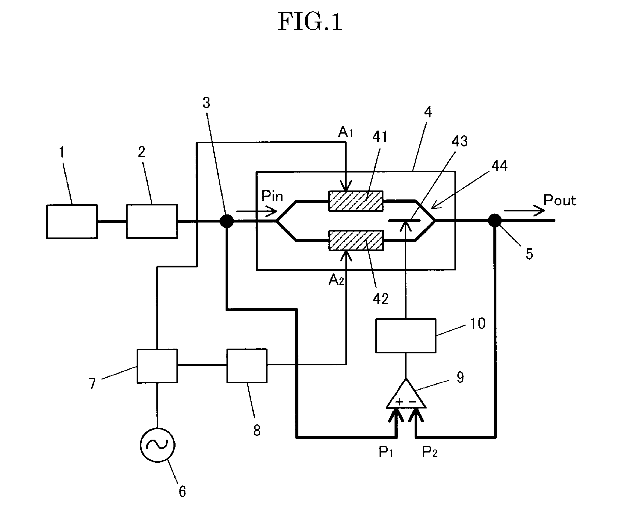
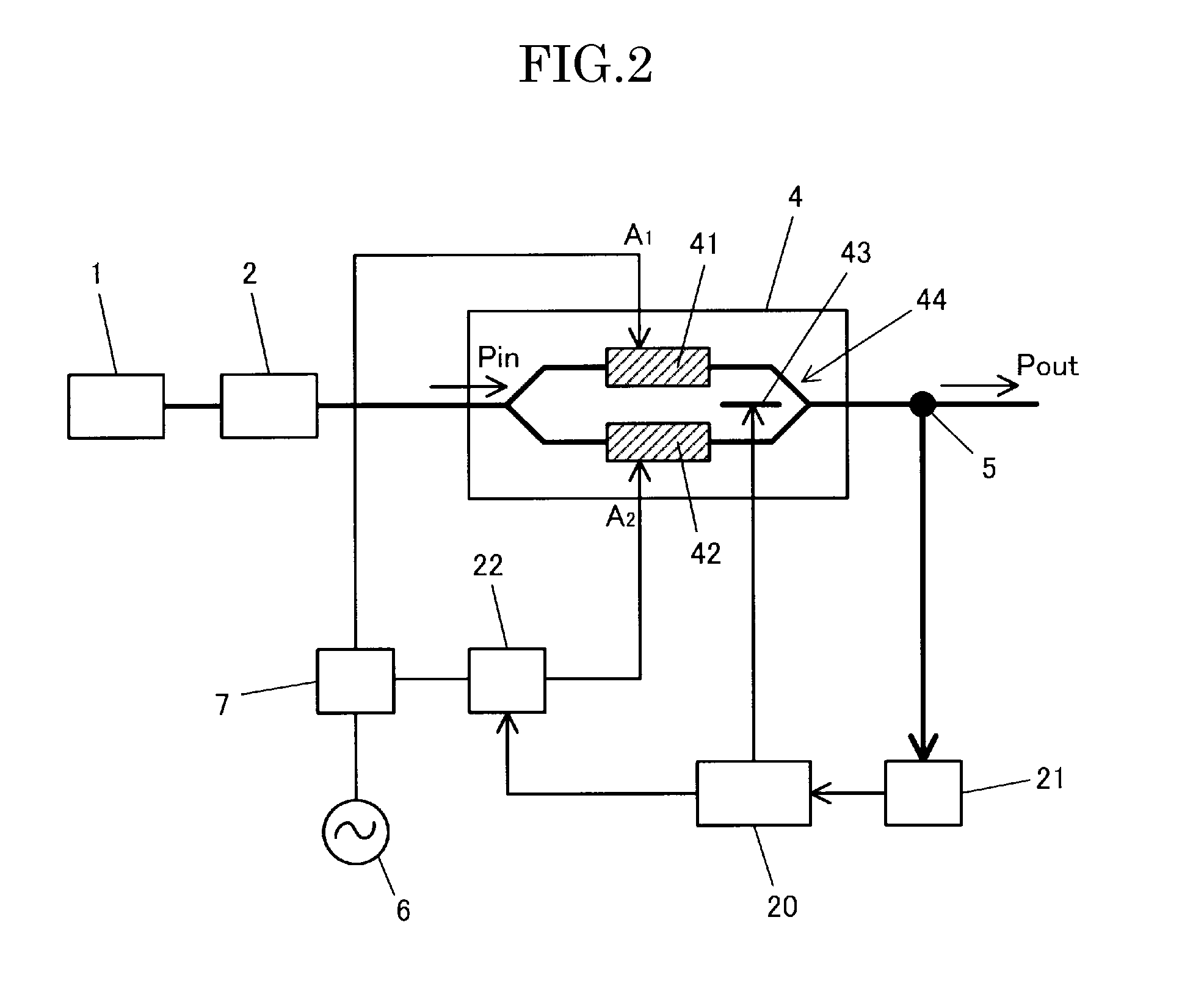
[0034]An optical frequency comb generating device, an optical pulse generating device using the optical frequency comb generating device, an optical frequency comb generating method, and an optical pulse generating method using the optical frequency comb generating method according to the invention will be described below in detail. In FIG. 2, the same reference numerals as in FIG. 1 represent the same members.

[0035]One feature of the invention is to employ a control method for which calibration, which is a problem in the control method according to the related art, is not required and which does not depend on the absolute value of optical power to be monitored.

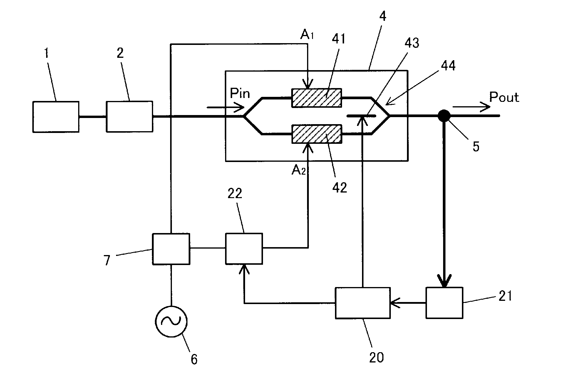
[0036]As shown in FIG. 2, an optical frequency comb generating device according to the invention includes a substrate having an electro-optical effect, a Mach-Zehnder type optical waveguide 44 formed on the substrate, two optical modulation parts 41 and 42 independently modulating optical waves propagating in two branch waveg...


PUM

PropertyMeasurementUnit
phaseaaaaaaaaaa
voltage amplitudeaaaaaaaaaa
optical frequencyaaaaaaaaaa

Abstract

The optical frequency comb generating device having two optical modulation parts 41 and 42 independently modulating optical waves propagating in two branch waveguides and a phase regulator 43 controlling a phase difference between the optical waves includes amplitude adjusting means 22 for adjusting a voltage amplitude of the RF signal supplied to at least one of the optical modulation parts, monitoring means 21 for monitoring the intensity Pout of the output light beam, and a bias control circuit 20 that controls the amplitude adjusting means to change a difference in voltage amplitude between the RF signals supplied to each optical modulation part, that detects a variation of the output light beam corresponding to the variation of the difference in voltage amplitude from the output signal of the monitoring means, and that controls the phase regulator on the basis of the detection result to adjust the phase difference.

Description

TECHNICAL FIELD[0001]The present invention relates to an optical frequency comb generating device and an optical pulse generating device using the same, and an optical frequency comb generating method and an optical pulse generating method using the same, and more particularly, to an optical frequency comb generating device which employs an optical modulator including two optical modulation parts that independently modulate optical waves propagating in two branch waveguides of a Mach-Zehnder type optical waveguide and a phase regulator that controls a phase difference between the optical waves propagating in the two branch waveguides, an optical pulse generating device employing the optical frequency comb generating device, an optical frequency comb generating method using the optical modulator, and an optical pulse generating method using the optical frequency comb generating method.BACKGROUND ART[0002]An optical frequency comb generating method of simultaneously generating plural ...

Claims


Application Information

Patent Timeline
Patent Type & Authority Applications(United States)
IPC IPC(8): G02F1/035
CPCG02F1/0123G02F2001/212G02F2203/56G02F1/2255H04B10/50572H04B10/50575H04B10/50577H04B10/5053G02F2201/58G02F1/212
Inventor SUDO, MASAAKIMURE, MASAHITO
Owner SUMITOMO OSAKA CEMENT CO LTD
Why Eureka
Try Eureka