Axial machining device

a technology of axial machining and machining parts, which is applied in the direction of feeding apparatus, drilling machines and methods, electrical apparatus, etc., can solve the problems of generating heat and noise, reducing the service life of the bearing, and not always achieving the optimum vibratory frequency for good swarf fragmentation

Active Publication Date: 2013-02-28
MITIS
View PDF22 Cites 15 Cited by
  • Summary
  • Abstract
  • Description
  • Claims
  • Application Information

AI Technical Summary

Benefits of technology

[0010]The invention thus provides an axial machining device comprising a tool-carrier spindle rotatable in a housing, the housing housing a transmission system for causing the spindle to advance automatically relative to the housing under the effect of the tool-carrier spindle being driven in rotation, the transmission system including an advance gearwheel screwed onto the spindle.

Problems solved by technology

That gives rise to friction on the cams, thereby generating heat and noise.
In addition, the optimum vibratory frequency for good fragmentation of swarf is not always obtained because the frequency is an integer multiple of the speed of rotation differential between the advance gearwheel and either the spindle or the housing, which differential is directly related to the number of oscillations of the cam.
In order to avoid that drawback, the spring must be very stiff, which can lead to the bearing being overdimensioned.
That gives rise to increased costs and size.
Furthermore, the device is fitted to the end of the spindle, under the advance system, thereby adding to overall size and leading to greater complexity.

Method used


Image

  • Axial machining device
  • Axial machining device
  • Axial machining device

Examples


Embodiment Construction

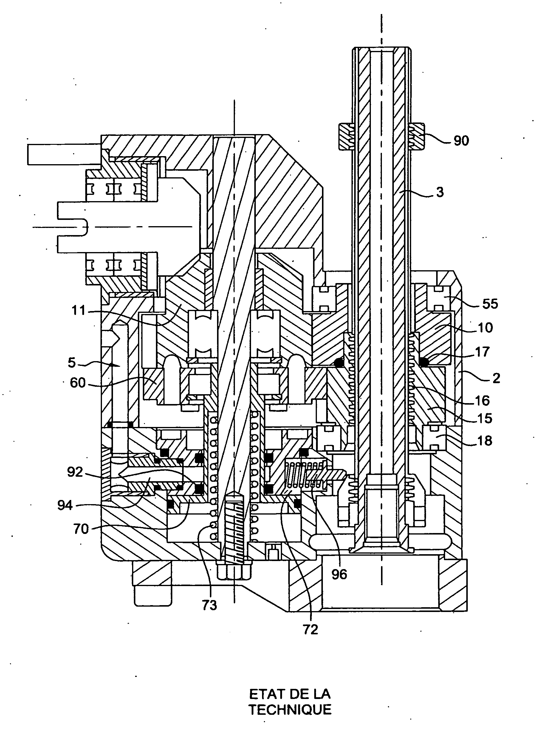
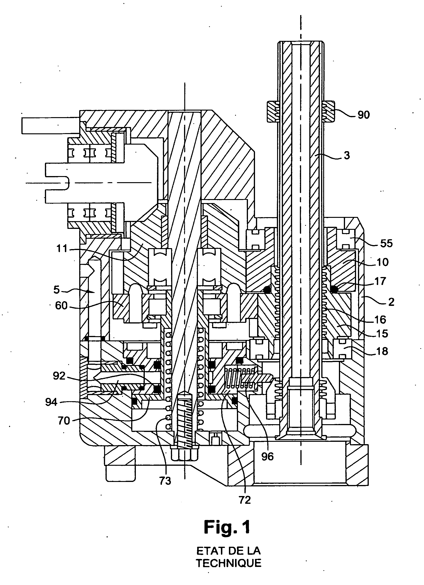
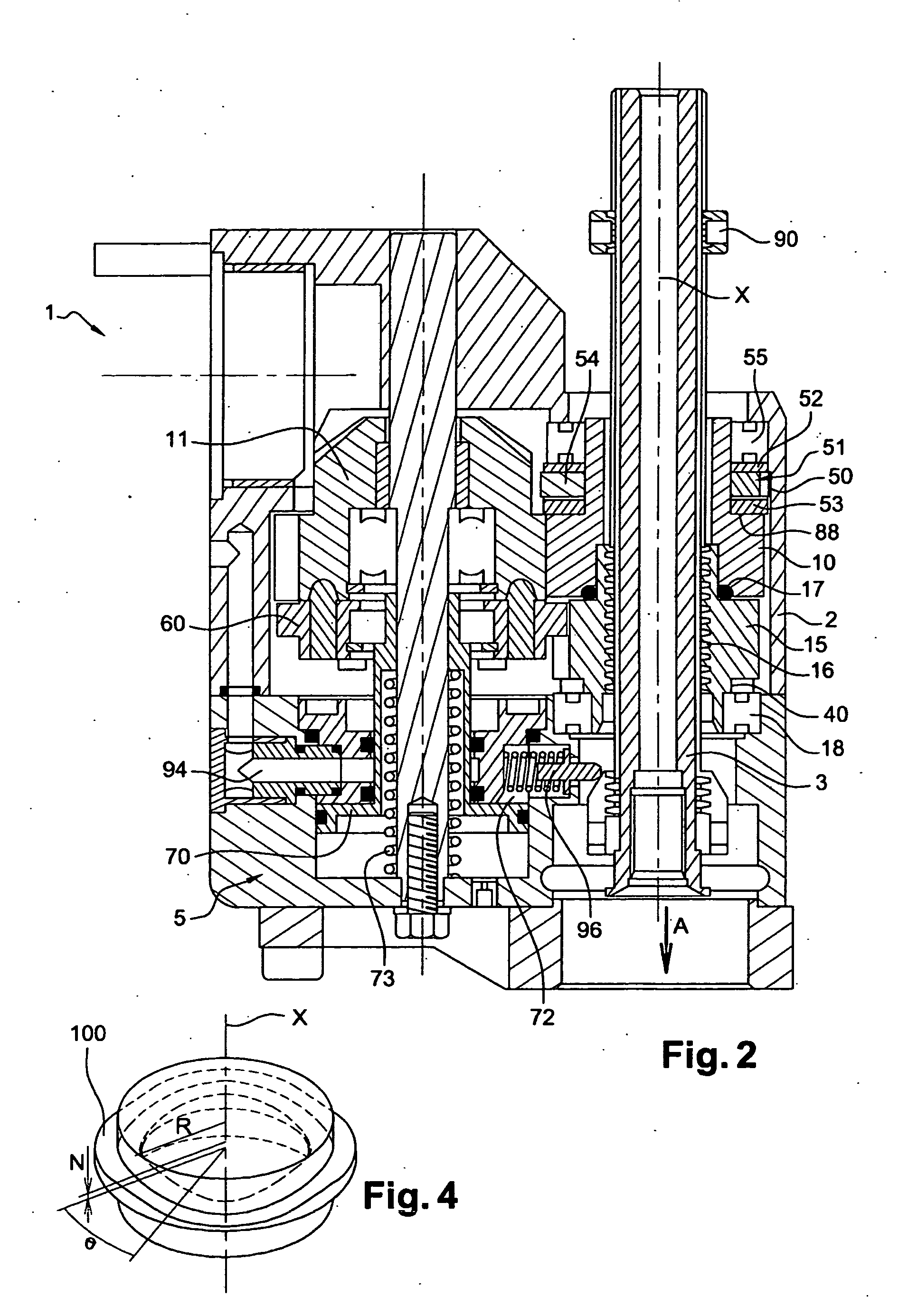
[0046]The machining device in accordance with the invention that is shown in FIG. 2, in particular a drilling device, comprises a housing 2 that houses part of a tool-carrier spindle 3, and a system 5 for automatically driving and advancing the spindle 3. The system 5 is coupled to a drive motor 112 shown in FIGS. 5 to 7, which motor may be a pneumatic motor, for example. The spindle 3 drives a drill bit or a cutter (not shown) so as to perform axial machining, e.g. drilling.

[0047]By way of example, the system 5 is similar to that described in patent application FR 2 881 366, and it comprises a rotary gearwheel 10 that rotates with the spindle 3 while allowing it to move axially relative thereto, the connection between the rotary gearwheel 10 and the spindle 3 being a sliding connection, for example, the spindle 3 possibly having fluting in which corresponding splines of the rotary gearwheel 10 are engaged.

[0048]The rotary gearwheel 10 is driven in rotation about an axis X by a driv...


PUM

PropertyMeasurementUnit
frictionaaaaaaaaaa
vibratory frequencyaaaaaaaaaa
frequencyaaaaaaaaaa

Abstract

The present invention provides an axial machining device comprising a tool-carrier spindle rotatable in a housing, the housing housing a transmission system causing the spindle to advance automatically relative to the housing under the effect of the tool-carrier spindle being driven in rotation, the transmission system including an advance gearwheel screwed onto the spindle, the device including a resilient return member urging the advance gearwheel in a first axial direction opposite to the advance direction of the spindle, and also including a first rolling bearing having rolling members rolling on an undulating raceway having an axial component, thereby periodically urging the advance gearwheel to move in a second direction opposite to the first, such that rotation of the spindle is accompanied by axial vibratory motion.

Description

FIELD OF THE INVENTION[0001]The present invention relates to devices for axial machining, such as drilling, boring, and milling, and more particularly it relates to compact devices incorporating means for imparting advance and infeed movement to the tool, e.g. a drill bit.BACKGROUND OF THE INVENTION[0002]Patent application FR 2 881 366 in the name of SETI TEC describes a drilling device including a drive gearwheel for driving a bit-carrier spindle in rotation and an advance gearwheel connected to the bit-carrier spindle via a threaded connection.[0003]A similar device is shown in FIG. 1. In this figure the numerical references are the same as those used below for referring to component parts that are identical or similar.[0004]Vibratory drilling devices are also known from the following publications: WO 2008 / 000935 A1, DE 10 2005 002 462 B4, U.S. Pat. No. 7,510,024 B2, FR 2 907 695, and US 2007 / 209813.[0005]Vibratory assistance serves to break up swarf and to increase the quality of...

Claims


Application Information

Patent Timeline
Patent Type & Authority Applications(United States)
IPC IPC(8): B23Q5/32B23B35/00B23B47/18
CPCB23B47/34Y10T408/03B23Q5/326B23Q5/323Y10T408/23Y10T408/6771Y10T408/6793Y10T408/68B23Q5/32
Inventor PEIGNE, GREGOIRE
Owner MITIS
Why Eureka
Try Eureka