Eureka AIR delivers breakthrough ideas for toughest innovation challenges, trusted by R&D personnel around the world.

Vehicle control system

Active Publication Date: 2013-02-28
HONDA MOTOR CO LTD
View PDF2 Cites 10 Cited by
  • Summary
  • Abstract
  • Description
  • Claims
  • Application Information

AI Technical Summary

Benefits of technology

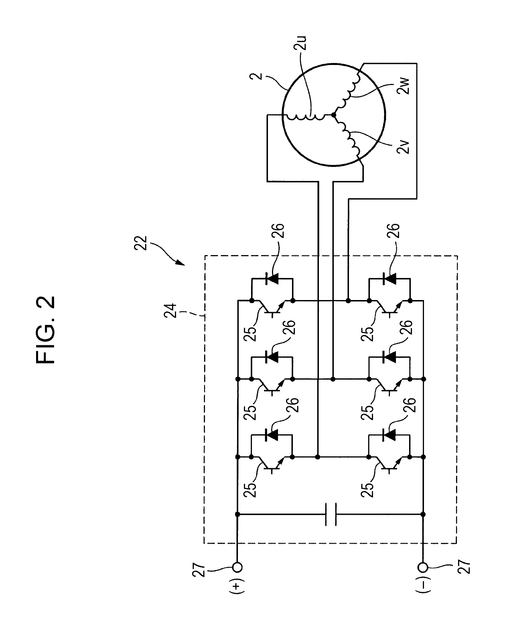
The patent text describes a technique to prevent overheat and malfunction of the inverter and to prevent the vehicle from rolling backward on an uphill in electric vehicles that enter a stall mode. This is achieved by detecting the temperature of a switching element in the inverter and replacing the driving force of the electric motor with a mechanical braking force of a brake system when the temperature reaches a certain threshold. The technique helps to lower the temperature of the switching element and prevents failure or malfunction of the inverter.

Problems solved by technology

Thus, the risk of overheat of the switching element increases.

Method used


Image

  • Vehicle control system
  • Vehicle control system
  • Vehicle control system

Examples


Embodiment Construction

[0016]The embodiments will now be described with reference to the accompanying drawings, wherein like reference numerals designate corresponding or identical elements throughout the various drawings.

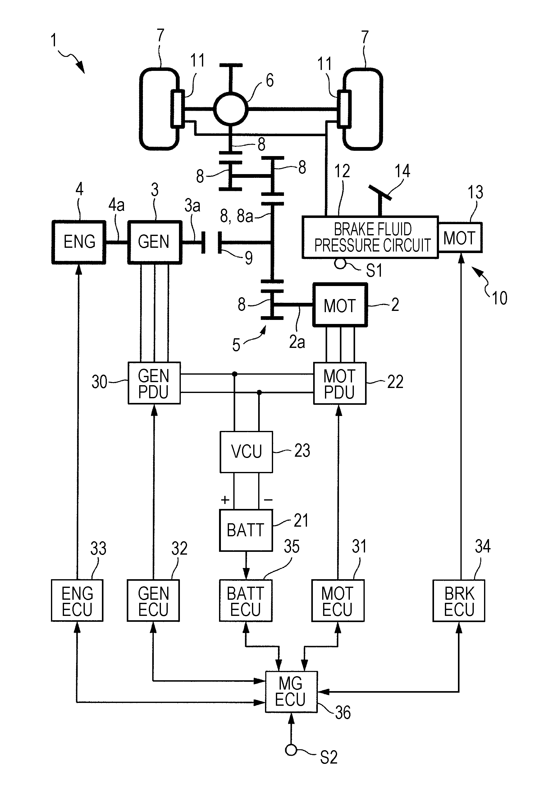
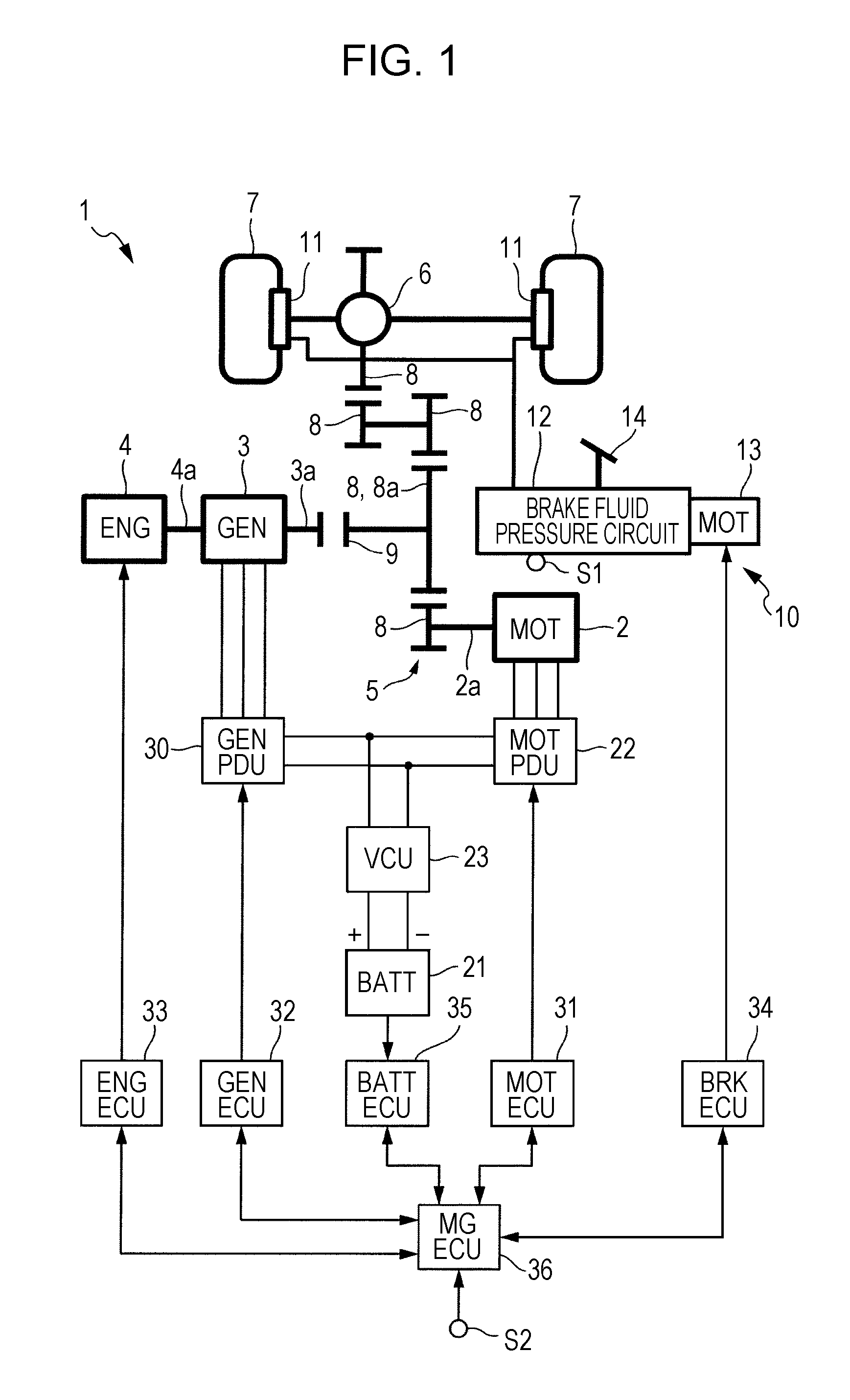
[0017]A brake control device of a vehicle according to a first exemplary embodiment of the technology is described below with reference to the accompanying drawings. As illustrated in FIG. 1, according to the present exemplary embodiment, an electric vehicle 1 (hereinafter also simply referred to as a “vehicle 1”) includes an electric motor 2 serving as a source of driving power of the vehicle 1, a generator 3, and an engine 4 that drives the generator. Note that according to the present exemplary embodiment, the engine 4 can also be used as a source of driving power of the vehicle 1. That is, according to the present exemplary embodiment, the vehicle 1 is an electric vehicle capable of operating as a series hybrid vehicle and a parallel hybrid vehicle.

[0018]The electric motor 2 includes...


PUM


Abstract

A vehicle control apparatus includes an electric motor, a source power supply circuit, an electric motor controller, a brake device, a brake controller, a stall determination device, a temperature detector, and a backward-rolling detector. The backward-rolling detector is configured to detect whether a vehicle is rolling backward. If rolling backward of the vehicle is detected by the backward-rolling detector while a brake torque instruction value is being generated, the brake torque instruction value is corrected so that the vehicle stops rolling backward.

Description

CROSS-REFERENCE TO RELATED APPLICATIONS [0001]The present application claims priority under 35 U.S.C. §119 to Japanese Patent Application No. 2011-188876, filed Aug. 31, 2011, entitled “Vehicle Control Apparatus.” The contents of this application are incorporated herein by reference in their entirety.BACKGROUND OF THE INVENTION [0002]1. Field of the Invention[0003]The present technology relates to a vehicle control system.[0004]2. Discussion of the Background[0005]In existing vehicles capable of traveling using only the driving force of an electric motor (such as hybrid motor vehicles), if, for example, the vehicles do not start moving on an uphill although the accelerator pedal is ON, that is, if the vehicles enter a stall mode, an electric current may continuously flow in a particular one of a plurality of switching elements of an inverter. Thus, the risk of overheat of the switching element increases. Accordingly, the following technique has been developed (refer to, for example,...

Claims


Application Information

Patent Timeline
IPC IPC(8): B60L15/00B60T7/12G06F11/30B60L50/16
CPCY02T10/6243B60K6/448B60W10/08B60W10/188B60W20/00Y02T10/7258B60W30/1843B60W2510/087B60W2510/182B60W2520/06B60W2710/083B60W30/18118Y02T10/62Y02T10/72
Inventor MATSUSHITA, MASANORI
Owner HONDA MOTOR CO LTD
Why Eureka
Eureka Blog
Learn More