Bicycle drive apparatus

a technology of drive apparatus and bicycle, which is applied in the direction of cycle equipment, process and machine control, instruments, etc., can solve the problems of increased load born by the rider, difficult gear shifting, and control incurs problems, and achieves smooth gear shifting operations, smooth gear shifting, and small chain tension

Active Publication Date: 2013-02-28
SHIMANO INC
View PDF4 Cites 37 Cited by
  • Summary
  • Abstract
  • Description
  • Claims
  • Application Information

AI Technical Summary

Benefits of technology

[0016]In accordance with an eighth aspect, the bicycle drive apparatus according to any one of the first to sixth aspects is provided such that the transmission is an external transmission. An external transmission is a transmission in which gear shifting is accomplished by moving the chain between sprockets using a derailleur. A front derailleur that moves the chain between sprockets of the crank axle and/or a rear derailleur that moves the chain between sprockets of the rear wheel are operated with a wire (cable) extending from a shifter or an electric motor in order to change gears. With this external transmission, a gear shifting operation is not adversely affected when some degree of tension exists in the chain, but gear shifting is difficult when an excessive amount of tension exists in the chain. However, with the present invention, gear shifting operations are smooth because they are executed when the crank is in the prescribed range including the top and bottom dead centers such that excessive tension does not exists in the chain during the gear shifting operations.
[0017]In accordance with a ninth aspect, the bicycle drive apparatus according to any one of the first to eighth aspects is provided such that the drive assistance electric motor is configured to dr

Problems solved by technology

With the control disclosed in Japanese Laid-Open Patent Publication No. 2004-268854, since the supply of the assisting power is limited such that the assisting power is equal to or smaller than a prescribed value during a prescribed period spanning before and after the gear shifting operation, the contr

Method used


Image

  • Bicycle drive apparatus
  • Bicycle drive apparatus
  • Bicycle drive apparatus

Examples


Embodiment Construction

[0032]Selected embodiments will now be explained with reference to the drawings. It will be apparent to those skilled in the art from this disclosure that the following descriptions of the embodiments are provided for illustration only and not for the purpose of limiting the invention as defined by the appended claims and their equivalents.

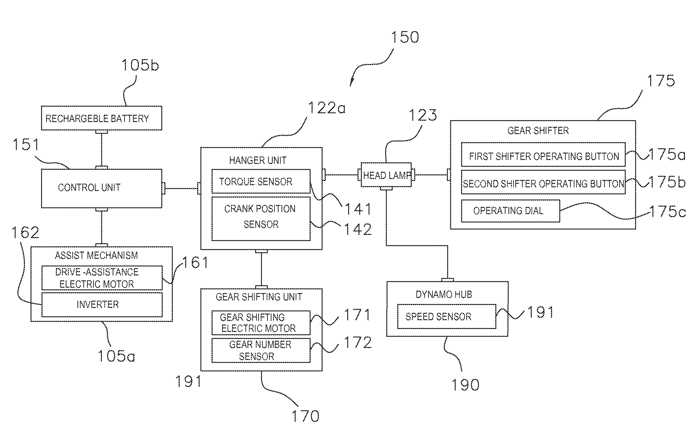
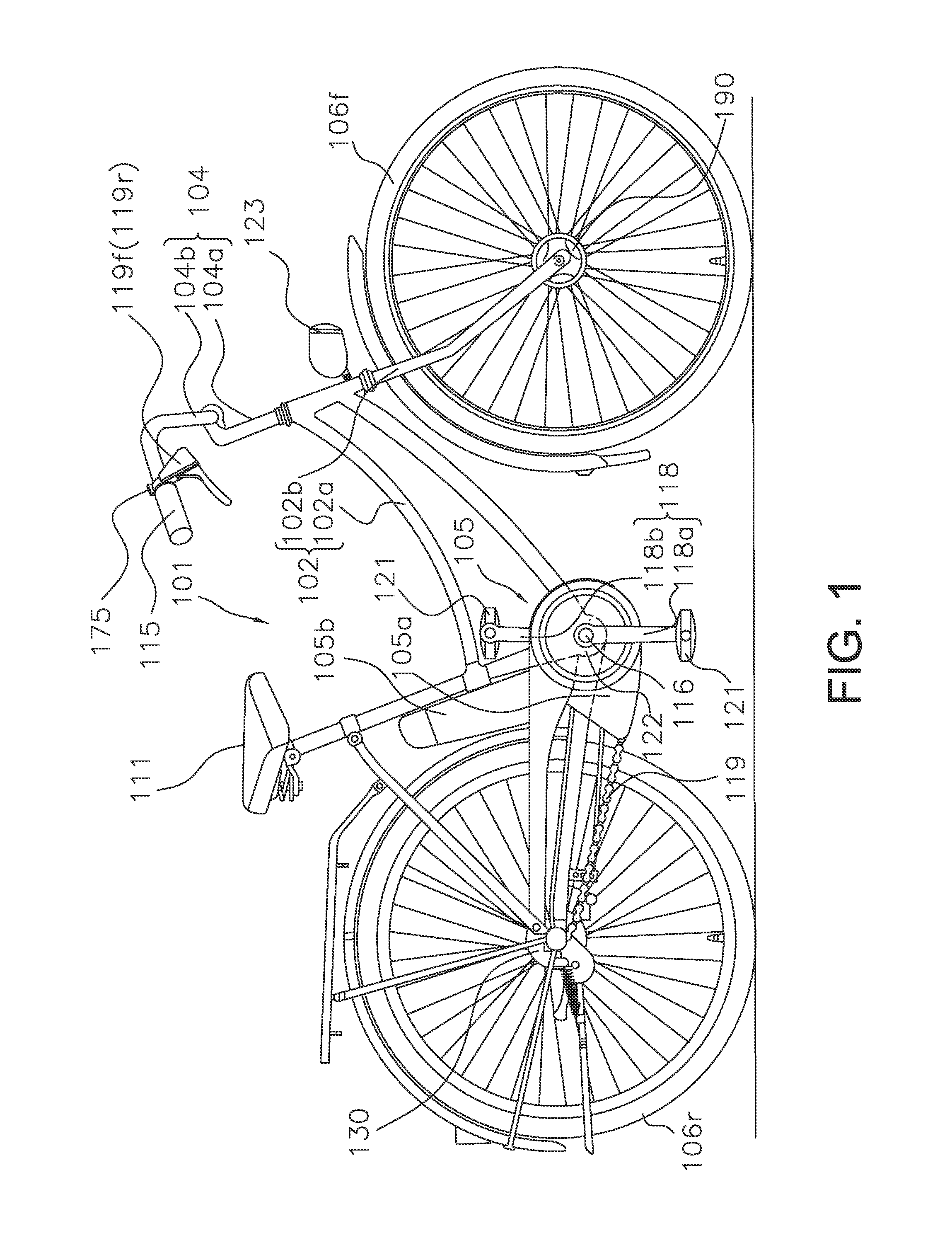
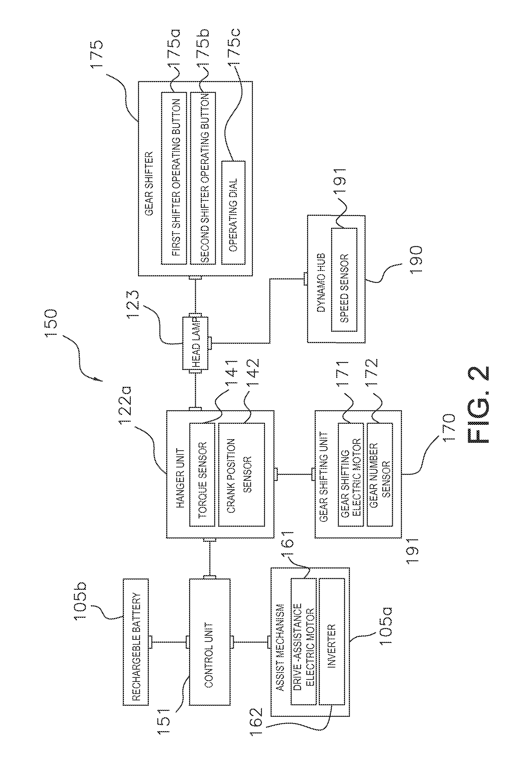
[0033]FIG. 1 shows a bicycle 1 that employs a first embodiment of the present invention. The bicycle 1 is an assisted bicycle configured to assist a rider by using an assist mechanism 105a to supplement a drive three (e.g., a pedaling force) imparted by the rider. The bicycle 101 comprises a frame 102 having a frame body 102a and a front fork 102b, a handlebar unit 104, a drive unit 105, a front wheel 106f, a rear wheel 106r, a front brake device and a rear brake device not shown in the figure, and a headlamp 123. The bicycle 101 also has the electrical system 150 shown in FIG. 2, which comprises a plurality of electrical components for the bicycl...


PUM


Abstract

A bicycle drive apparatus includes a bicycle crankset, a bicycle transmission, a drive assistance electric motor and a microcomputer. The microcomputer includes an output control section. The output control section has a first control and a second control that makes an output of the drive assistance electric motor smaller than an output of the drive assistance electric motor occurring during the first control only upon determining a crank arm of the bicycle crankset is positioned within a prescribed range of at least one of a top dead center position and a bottom dead center position of the bicycle crankset. The output control section is configured to vary the output of the drive assistance electric motor according to a pedaling force. The output control section switches from the first control to the second control upon receiving a shift command to shift the transmission.

Description

CROSS-REFERENCE TO RELATED APPLICATIONS[0001]This application claims priority under 35 U.S.C. §119 to Japanese Patent Application No. 2011-186594, filed Aug. 29, 2011. The entire disclosure of Japanese Patent Application No. 2011-186594 is hereby incorporated herein by reference.BACKGROUND[0002]1. Field of the Invention[0003]The present invention relates to a bicycle drive apparatus that controls an electrically assisted bicycle. More specifically, the present invention relates to a bicycle drive apparatus that controls a bicycle having an electric motor for riding assistance and a transmission.[0004]2. Background Information[0005]Recently, electrically assisted bicycles that assist riding by supplementing a person's pedaling force with a motor drive force are becoming popular. Japanese Laid-Open Patent Publication No. 2004-268854 discloses a control enabling the transmission to smoothly conduct a gear shifting operation in an electrically assisted bicycle equipped with a transmissi...

Claims


Application Information

Patent Timeline
IPC IPC(8): G06F17/00B62K11/00
CPCB62K23/02B62M6/45B60L50/20B60L2200/12
Inventor KOMATSU, ATSUSHI
Owner SHIMANO INC
Why Eureka
Try Eureka