Power tool dust collecting device and power tool

a technology of dust collection device and power tool, which is applied in the direction of manufacturing tools, cleaning filter means, working accessories, etc., can solve the problems of adversely affecting the flow of air, reducing the suction amount of outside air, etc., and achieves the effect of ensuring the smooth flow of air, elastic deformation, and suitable dust collection efficiency

Active Publication Date: 2013-03-07
MAKITA CORP
View PDF7 Cites 29 Cited by
  • Summary
  • Abstract
  • Description
  • Claims
  • Application Information

AI Technical Summary

Benefits of technology

[0012]In the first and twelfth aspects of the invention, since the blocking ring including the ventilating portion is employed, the flow of air can be maintained without a decrease in the suction force even if the suction head is, for example, tilted. Therefore, a suitable dust collecting efficiency can be obtained.
[0013]In the second aspect of the invention, in addition to the effect of the first aspect, the V-shaped slit is provided as the ventilating portion. Thus, a suitable ventilating portion that maintains the flow of air while ensuring the elastic deformation of the blocking ring can be...

Problems solved by technology

However, if the flexibility of the suction head is increased, the suction head is in close contact with the ...

Method used


Image

  • Power tool dust collecting device and power tool
  • Power tool dust collecting device and power tool
  • Power tool dust collecting device and power tool

Examples


first embodiment

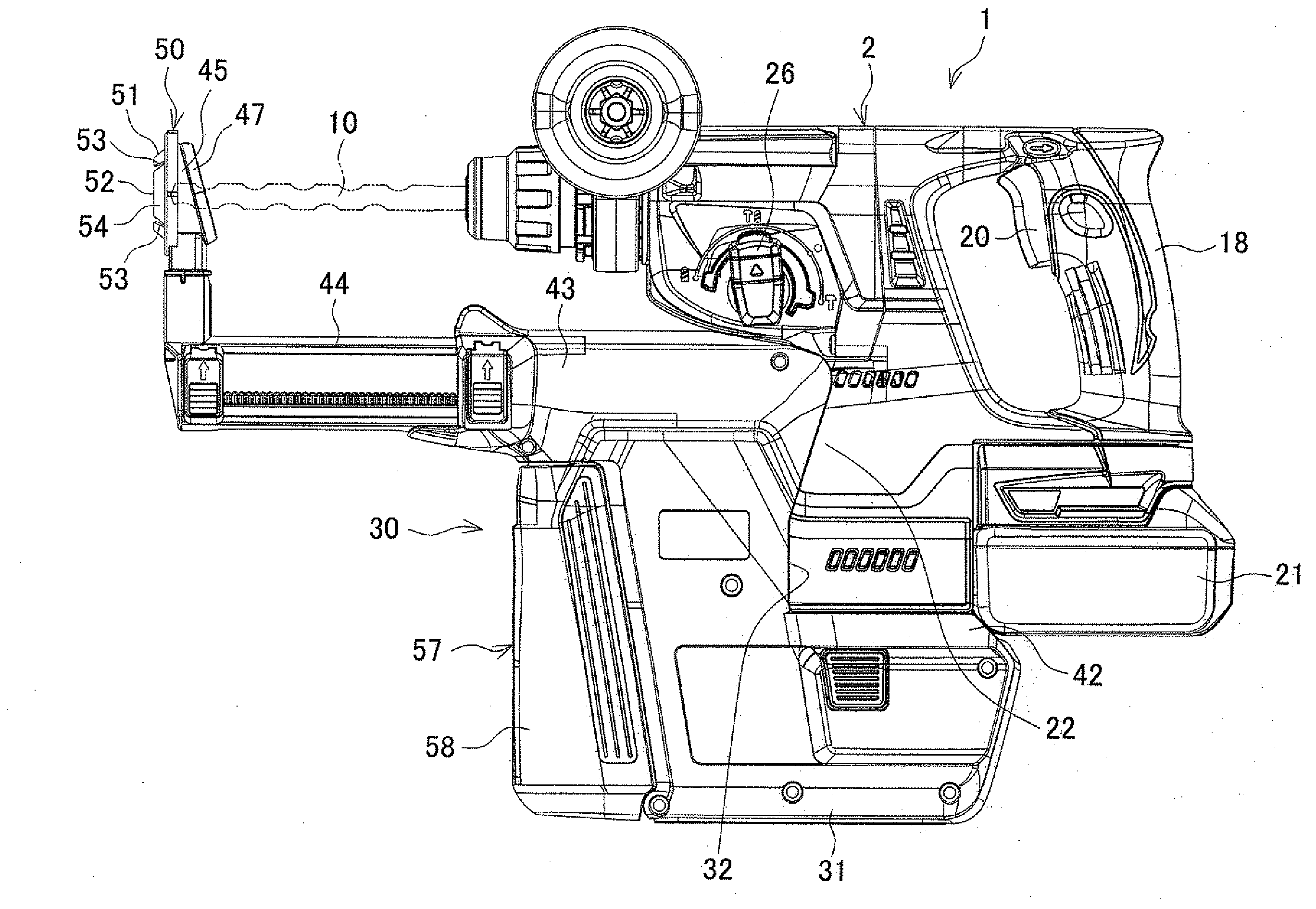
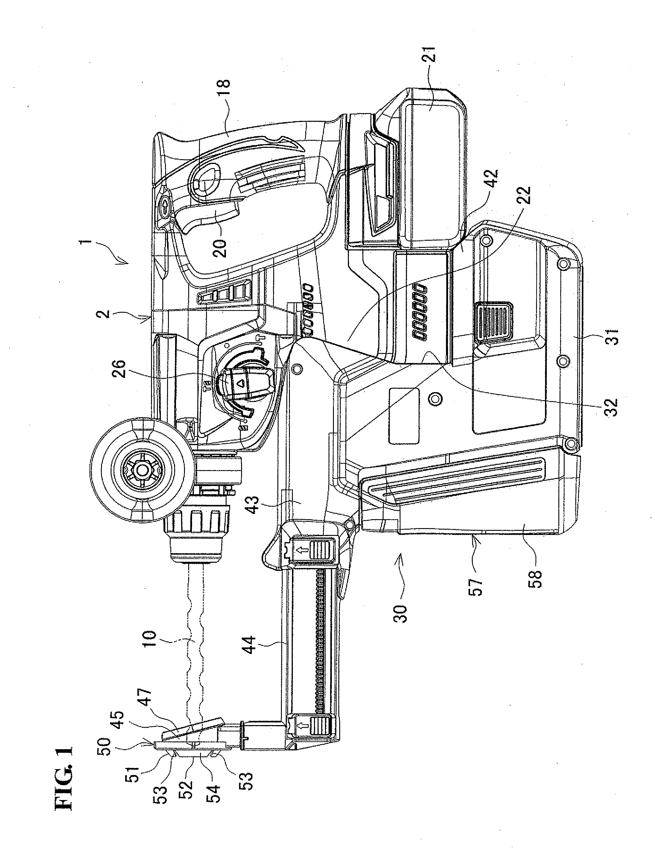
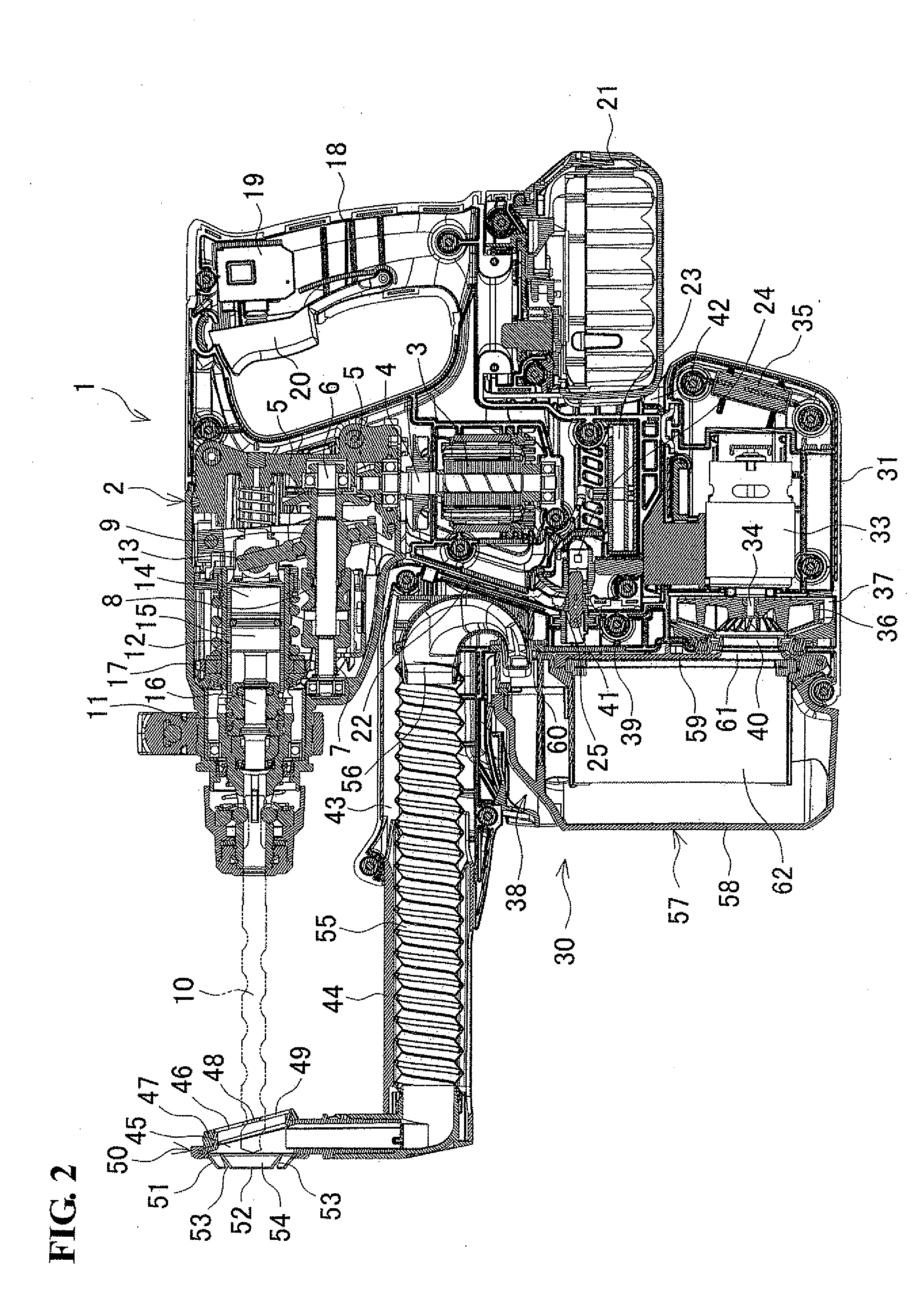
[0032]FIG. 1 is a side view of a hammer drill, as one example of a power tool, equipped with a power tool dust collecting device (hereinafter simply referred to as “dust collecting device”), and FIG. 2 is a vertical-sectional view of the hammer drill.

[0033]In a hammer drill 1, a housing 2 formed by assembling a pair of left and right half housings accommodates a motor 3 in a lower portion on the front side (front side being the left side in FIGS. 1 and 2), such that an output shaft 4 is directed upward. An intermediate shaft 6 is provided above the motor 3 and torque is transmitted to the intermediate shaft 6 via bevel gears 5. The intermediate shaft 6 is provided with a first gear 7, a clutch 8, and a boss sleeve 9 in this order from the front. Above the intermediate shaft 6, a tool holder 11 to which a bit 10 as a tip end tool can be inserted at the tip end is rotatably supported in parallel to the intermediate shaft 6. An arm 13 is mounted on the exterior of the boss sleeve 9 wit...

second embodiment

[0062]Another embodiment of the present invention will be described with reference to FIGS. 7 to 13. FIGS. 7 and 8 show a state where a power tool dust collecting device 130 (hereinafter referred to as dust collecting device 130) is mounted on a hammer drill 101, and FIG. 9 shows the dust collecting device 130. The hammer drill 101 is one example of the power tool according to the present invention and includes a body housing 102 made of resin. In FIGS. 7 and 8, the left side is the front side of the body housing 102, and the right side is the rear side of the body housing 102. As shown in FIG. 8, a motor 104 with an output shaft 103 directed upward is accommodated in a lower portion on the front side in the body housing 102. Above the output shaft 103 in the body housing 102, an intermediate shaft 105 is rotatably supported in a direction that intersects with the output shaft 103, so that torque is transmitted from the output shaft 103 to the intermediate shaft 105 via bevel gears ...


PUM


Abstract

In a power tool dust collecting device, a blocking ring that is subject to elastic deformation upon contact with a workpiece surface for blockage between a suction head and the workpiece surface is provided to the front surface of the suction head to be brought into contact with the workpiece surface. The blocking ring has a ventilating portion (a V-shaped slit) that ensures the flow of air to the suction head regardless of whether the elastic deformation has occurred.

Description

BACKGROUND OF THE INVENTION[0001]This application claims the benefit of Japanese Patent Application Number 2011-195275 filed on Sep. 7, 2011 and Japanese Patent Application No. 2011-220375 filed on Oct. 4, 2011, the entirety of which is incorporated by reference.TECHNICAL FIELD[0002]The present invention relates to a power tool dust collecting device that is mounted to a power tool such as an electric drill or a hammer drill and a power tool equipped with the dust collecting device.BACKGROUND ART[0003]A power tool such as an electric drill or a hammer drill is equipped with a dust collecting device that collects and recovers dust generated from a workpiece upon drilling and the like. As disclosed in the specification of German Patent Application Publication No. 102006039969, the dust collecting device includes, at a tip end of an arm fanning a dust collecting path, a cylindrical suction head through which a tip end tool mounted to the power tool penetrates and of which a side for co...

Claims


Application Information

Patent Timeline
IPC IPC(8): A47L9/10
CPCB23Q11/0046B28D7/02Y02P70/171
Inventor YOSHIKANE, KIYONOBUMACHIDA, YOSHITAKA
Owner MAKITA CORP
Why Eureka
Try Eureka