Components with re-entrant shaped cooling channels and methods of manufacture

a cooling channel and component technology, applied in the direction of machines/engines, lighting and heating apparatus, forging/pressing/hammering apparatus, etc., can solve the problems of low heat transfer rate, reduced engine efficiency, and non-uniform component temperature profiles

Active Publication Date: 2013-03-07
GENERAL ELECTRIC CO
View PDF3 Cites 16 Cited by
  • Summary
  • Abstract
  • Description
  • Claims
  • Application Information

AI Technical Summary

Problems solved by technology

However, the combustion gases heat the various components along their flowpath, which in turn requires cooling thereof to achieve an acceptably long engine lifetime.
This cooling process reduces engine efficiency, as the bled air is not used in the combustion process.
However, this cooling strategy typically results in comparatively low heat transfer rates and non-uniform component temperature profiles.
However, both the filling of the channels with a fugitive material, and the later removal of that material present potential problems for current micro-channel processing techniques.
Removal of the sacrificial filler involves potentially damaging processes of leaching, etching, or vaporization, and typically requires long times. Residual filler material is also a concern.

Method used


Image

  • Components with re-entrant shaped cooling channels and methods of manufacture
  • Components with re-entrant shaped cooling channels and methods of manufacture
  • Components with re-entrant shaped cooling channels and methods of manufacture

Examples


Embodiment Construction

[0028]The terms “first,”“second,” and the like, herein do not denote any order, quantity, or importance, but rather are used to distinguish one element from another. The terms “a” and “an” herein do not denote a limitation of quantity, but rather denote the presence of at least one of the referenced items. The modifier “about” used in connection with a quantity is inclusive of the stated value, and has the meaning dictated by context, (e.g., includes the degree of error associated with measurement of the particular quantity). In addition, the term “combination” is inclusive of blends, mixtures, alloys, reaction products, and the like.

[0029]Moreover, in this specification, the suffix “(s)” is usually intended to include both the singular and the plural of the term that it modifies, thereby including one or more of that term (e.g., “the passage hole” may include one or more passage holes, unless otherwise specified). Reference throughout the specification to “one embodiment,”“another ...


PUM

PropertyMeasurementUnit
widthsaaaaaaaaaa
depthsaaaaaaaaaa
pressureaaaaaaaaaa

Abstract

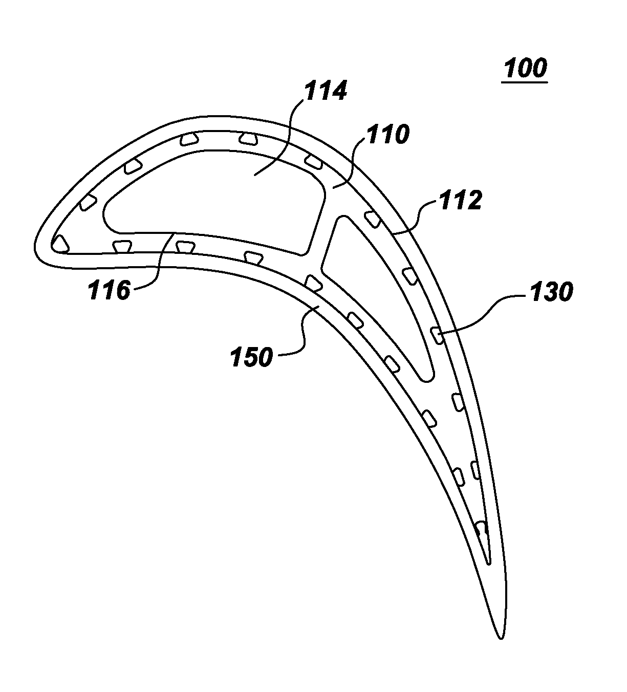
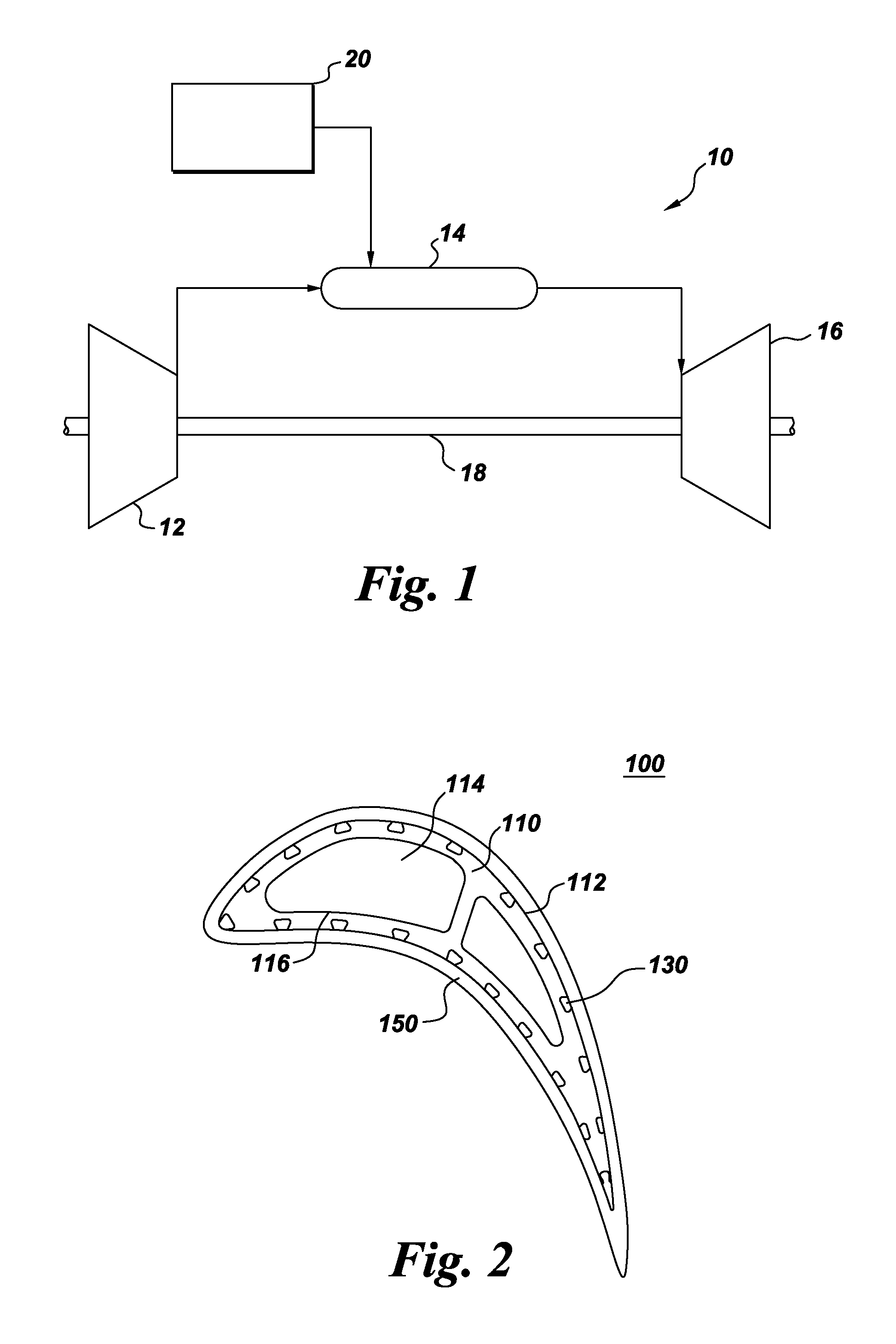
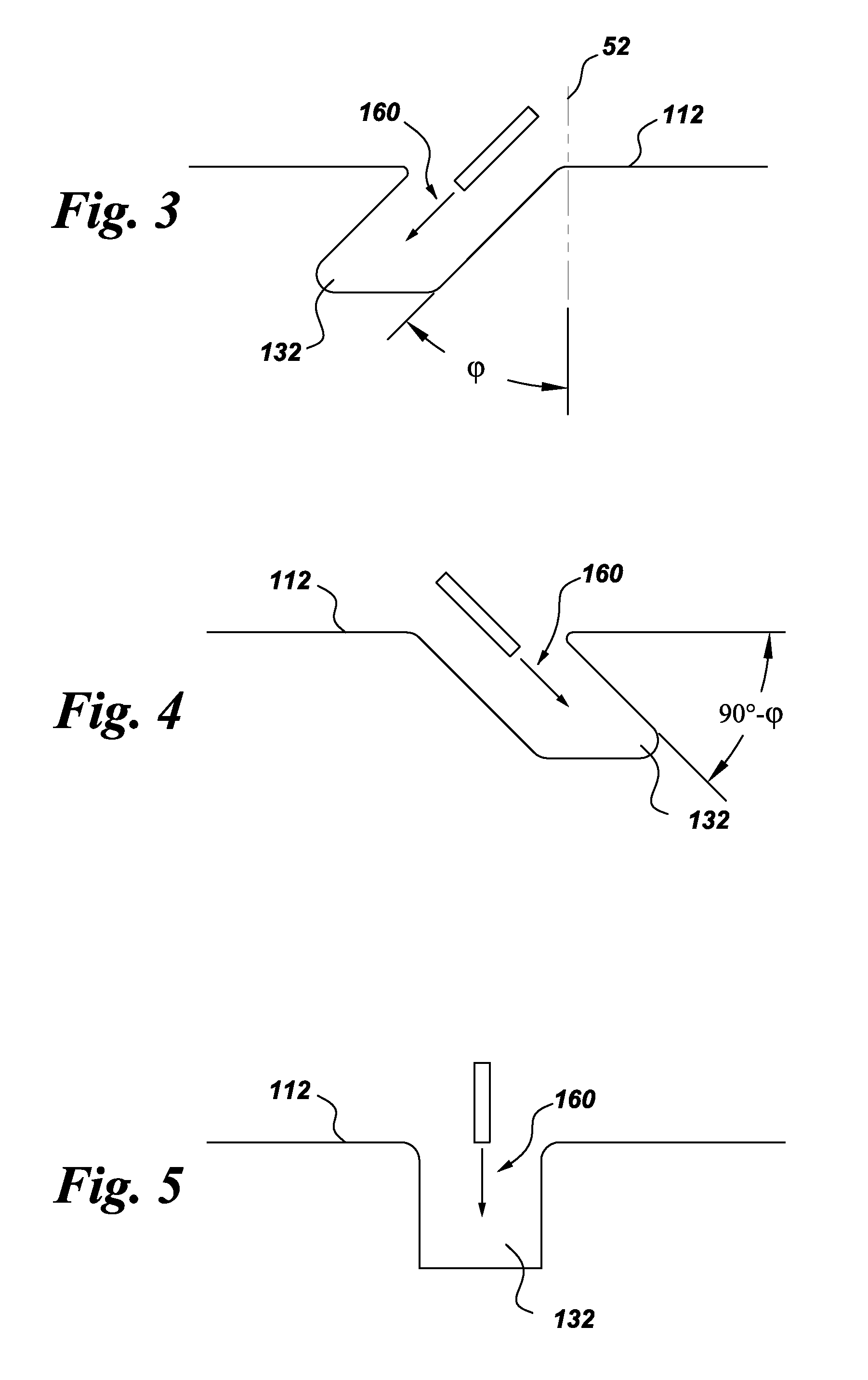
A method of fabricating a component is provided. The component includes a substrate that has at least one interior space. The method includes forming one or more grooves in the component. Each groove extends at least partially along an outer surface of the substrate and narrows at an opening thereof, such that each groove is re-entrant shaped. A cross-sectional area A of each groove is in a range of about 2 to about 3 times an area R=W*D, where W is the width of the opening and D is the depth of the re-entrant-shaped groove. Components with grooves formed in the substrate and components with grooves formed at least partially in a structural coating are also provided.

Description

CROSS REFERENCE TO RELATED APPLICATIONS[0001]This application is a continuation in part of U.S. patent application Ser. No. 12 / 943,624, Ronald Scott Bunker et al., entitled “Components with re-entrant shaped cooling channels and methods of manufacture,” which patent application is incorporated by reference herein in its entirety.BACKGROUND[0002]The invention relates generally to gas turbine engines, and, more specifically, to micro-channel cooling therein.[0003]In a gas turbine engine, air is pressurized in a compressor and mixed with fuel in a combustor for generating hot combustion gases. Energy is extracted from the gases in a high pressure turbine (HPT), which powers the compressor, and in a low pressure turbine (LPT), which powers a fan in a turbofan aircraft engine application, or powers an external shaft for marine and industrial applications.[0004]Engine efficiency increases with temperature of combustion gases. However, the combustion gases heat the various components along...

Claims


Application Information

Patent Timeline
Patent Type & Authority Applications(United States)
IPC IPC(8): F28F13/06C23C4/12B05D5/00B21D53/04F28F13/18
CPCY02T50/672Y02T50/67Y02T50/676B23P15/04B24C1/04C23C4/02Y10T29/4935B23P2700/13F01D5/186F05D2230/90C23C24/04Y10T29/49323C23C4/12Y02T50/60
Inventor BUNKER, RONALD SCOTTGRAY, DENNIS MICHAEL
Owner GENERAL ELECTRIC CO
Why Eureka
Try Eureka