Device cooperation system, image forming apparatus, and function providing method

Inactive Publication Date: 2013-03-07
PIXTRONIX INC +1
View PDF11 Cites 19 Cited by
  • Summary
  • Abstract
  • Description
  • Claims
  • Application Information

AI Technical Summary

Benefits of technology

[0010]The present invention provides a device cooperation system in w

Problems solved by technology

However, in patent document 1, it is not considered how to lim

Method used


Image

  • Device cooperation system, image forming apparatus, and function providing method
  • Device cooperation system, image forming apparatus, and function providing method
  • Device cooperation system, image forming apparatus, and function providing method

Examples


Embodiment Construction

[0036]A description is given, with reference to the accompanying drawings, of embodiments of the present invention.

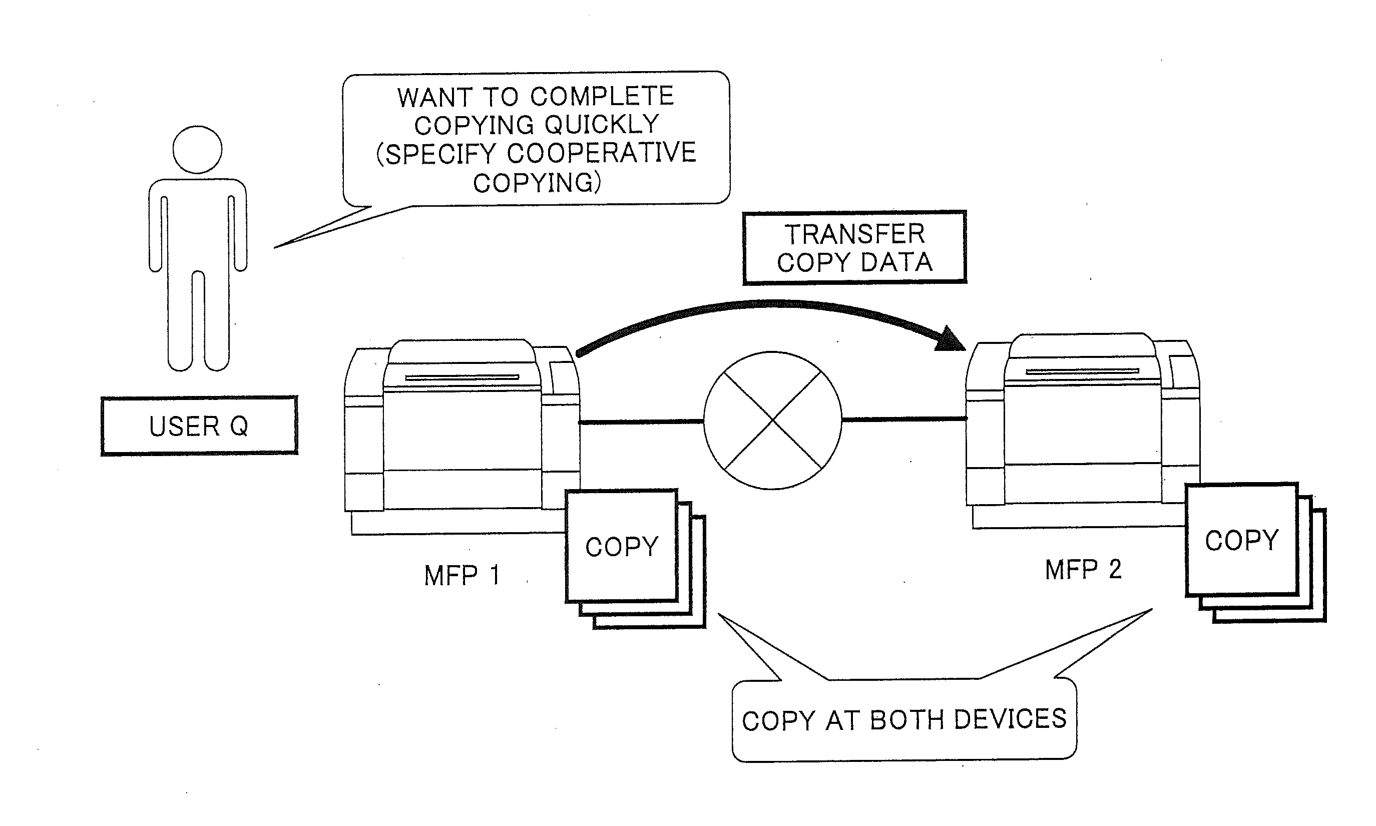
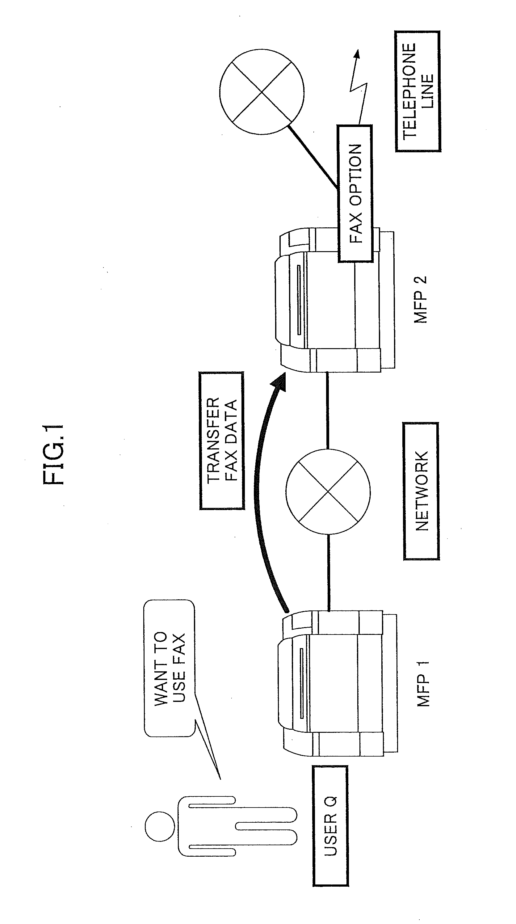
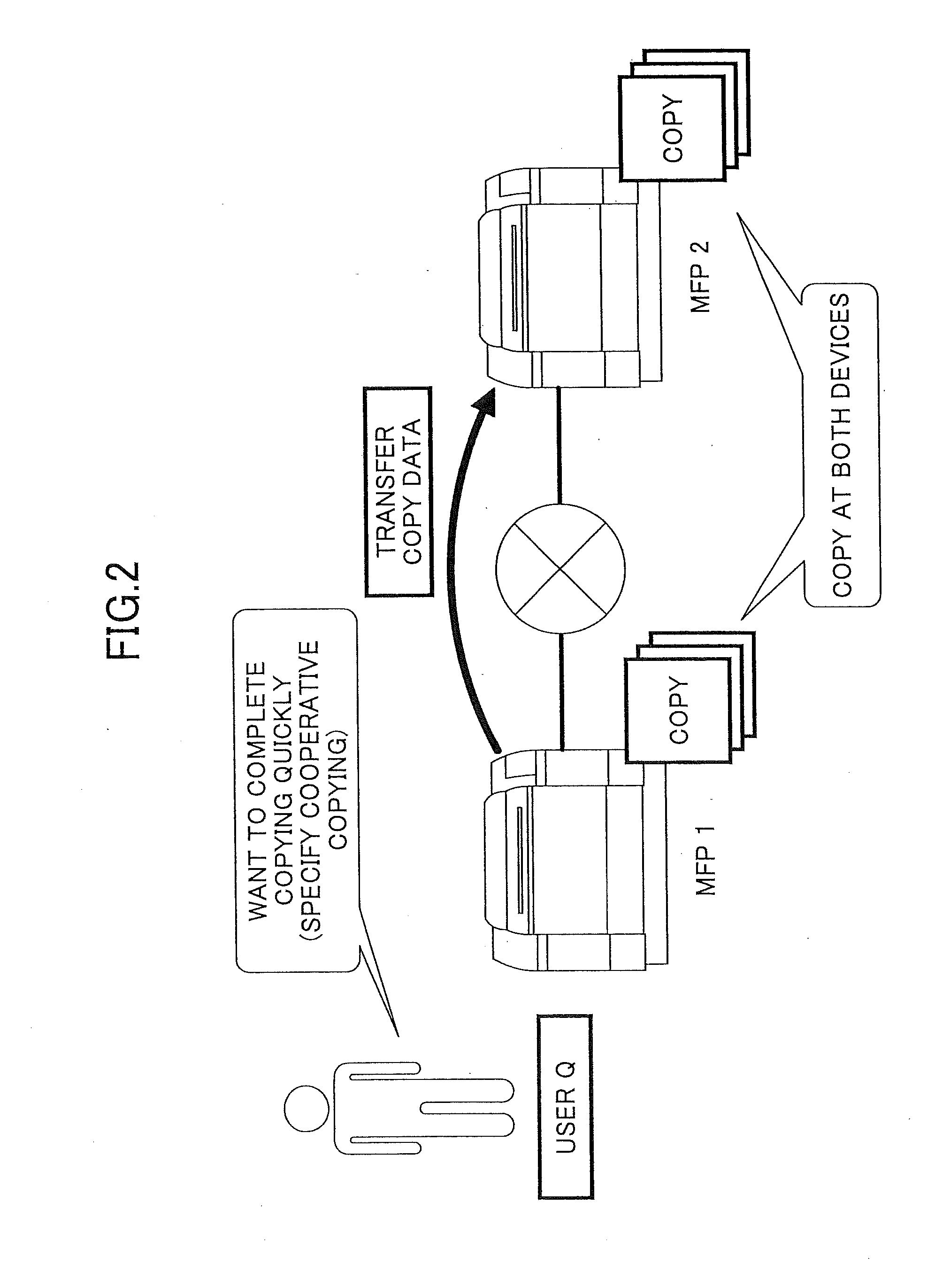
[0037]FIG. 3 schematically illustrates a device cooperation system 200 according to the present embodiment. An MFP (multifunction peripheral) 1 and an MFP 2 (hereinafter, referred to as “MFP 100” when not distinguished from each other) can execute a single job by cooperating with each other. This system in which plural devices provide functions to each other is referred to as the device cooperation system 200. A job that is executed by two or more MFPs in cooperation with each other is referred to as a device cooperation job. Furthermore, image data corresponding to one side of a sheet is referred to as one page, and the minimum unit of a sheet material is referred to as one page, regardless of single-sided printing or double-sided printing.

[0038]FIG. 3 schematically illustrates procedures performed by the MFP 1 and the MFP 2 for executing a device cooperation job of a ...


PUM


Abstract

In a device cooperation system, devices connected via a network take partial charge of providing a function. A first device acquires image data to be output; receives a condition used when the first device and a second device output the image data; stores a possible output amount that can be output by the first device; determines whether a total page number, which is obtained from the condition and a number of pages of the acquired image data, is less than or equal to the possible output amount; determines first and second output numbers to be respectively allocated to the first and second devices; sends the image data and the second output number to the second device; and updates the possible output amount according to a number output by the first and second devices.

Description

BACKGROUND OF THE INVENTION[0001]1. Field of the Invention[0002]The present invention relates to a device cooperation system in which plural devices connected via a network take partial charge of providing functions of the devices.[0003]2. Description of the Related Art[0004]There is known a processing format referred to as device cooperation, by which plural devices connected in a network cooperate with each other to execute a single job. Device cooperation means that plural devices take partial charge of providing functions necessary for a single job constituted by a series of processes starting from input to output.[0005]FIG. 1 illustrates an example of executing a job by device cooperation. An MFP (multifunction peripheral) 1 and an MFP 2 are connected to each other via a network. The MFP 1 does not have a fax function, but the MFP 2 has a fax function. A user Q wants to transmit image data by fax, but because the MFP 1 does not have a fax function, the user Q uses the MFP 1 to ...

Claims


Application Information

Patent Timeline
IPC IPC(8): G06K15/02
CPCG06F3/124G06F9/5011G06F3/1213G06F3/1219G06F3/1221Y02B60/142G06F3/1241G06F3/1271G06F3/1291Y02B60/1271G06F3/1239Y02D10/00
Inventor OHTA, SHINGO
Owner PIXTRONIX INC
Why Eureka
Try Eureka