Vehicle lighting device
a technology for vehicle lighting and diodes, which is applied in the direction of lighting support devices, fixed installations, lighting and heating apparatus, etc., can solve the problem of easy distortion of the optical distribution of light from light emitting diodes
- Summary
- Abstract
- Description
- Claims
- Application Information
AI Technical Summary
Benefits of technology
Problems solved by technology
Method used
Image
Examples
first embodiment
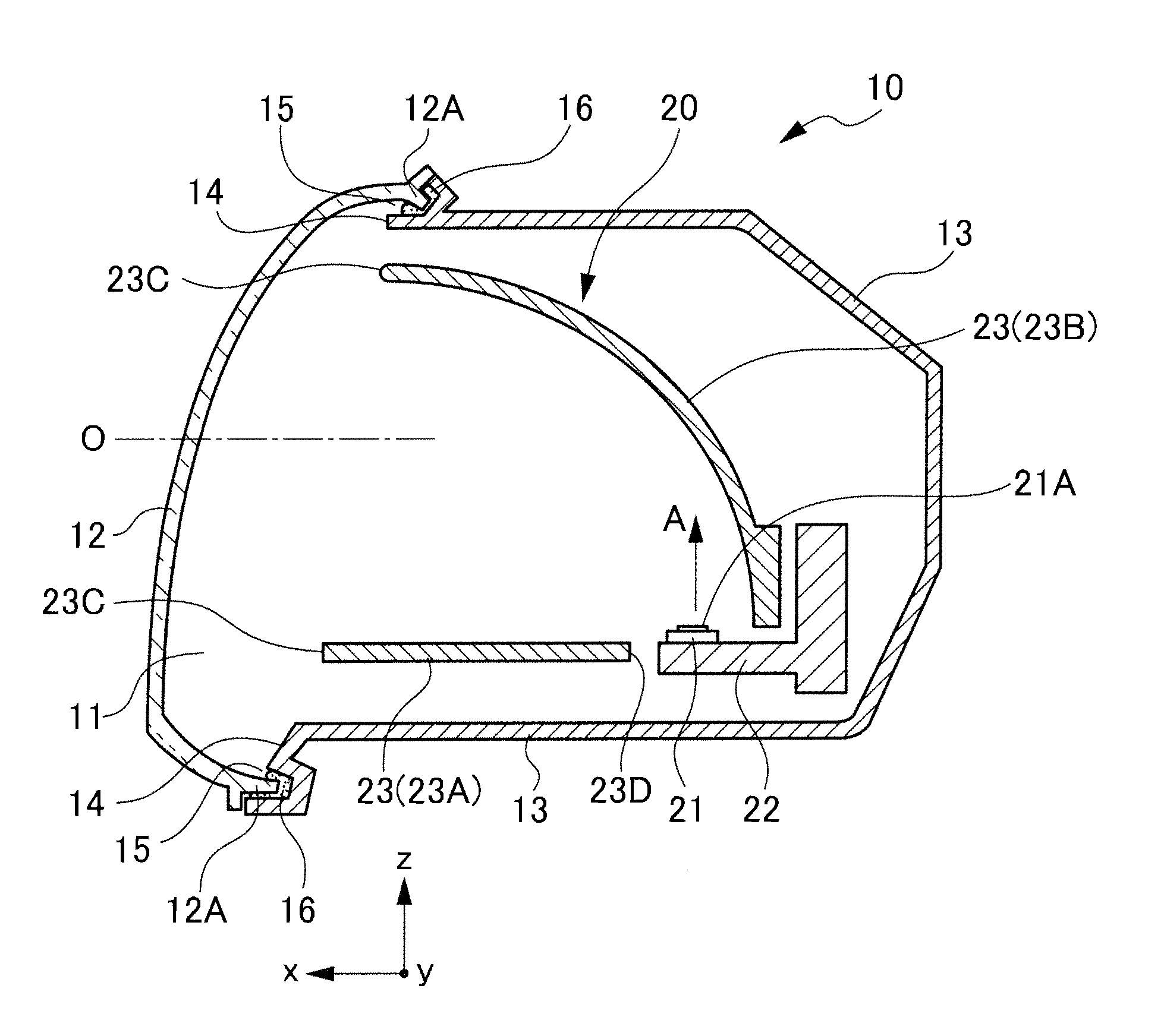
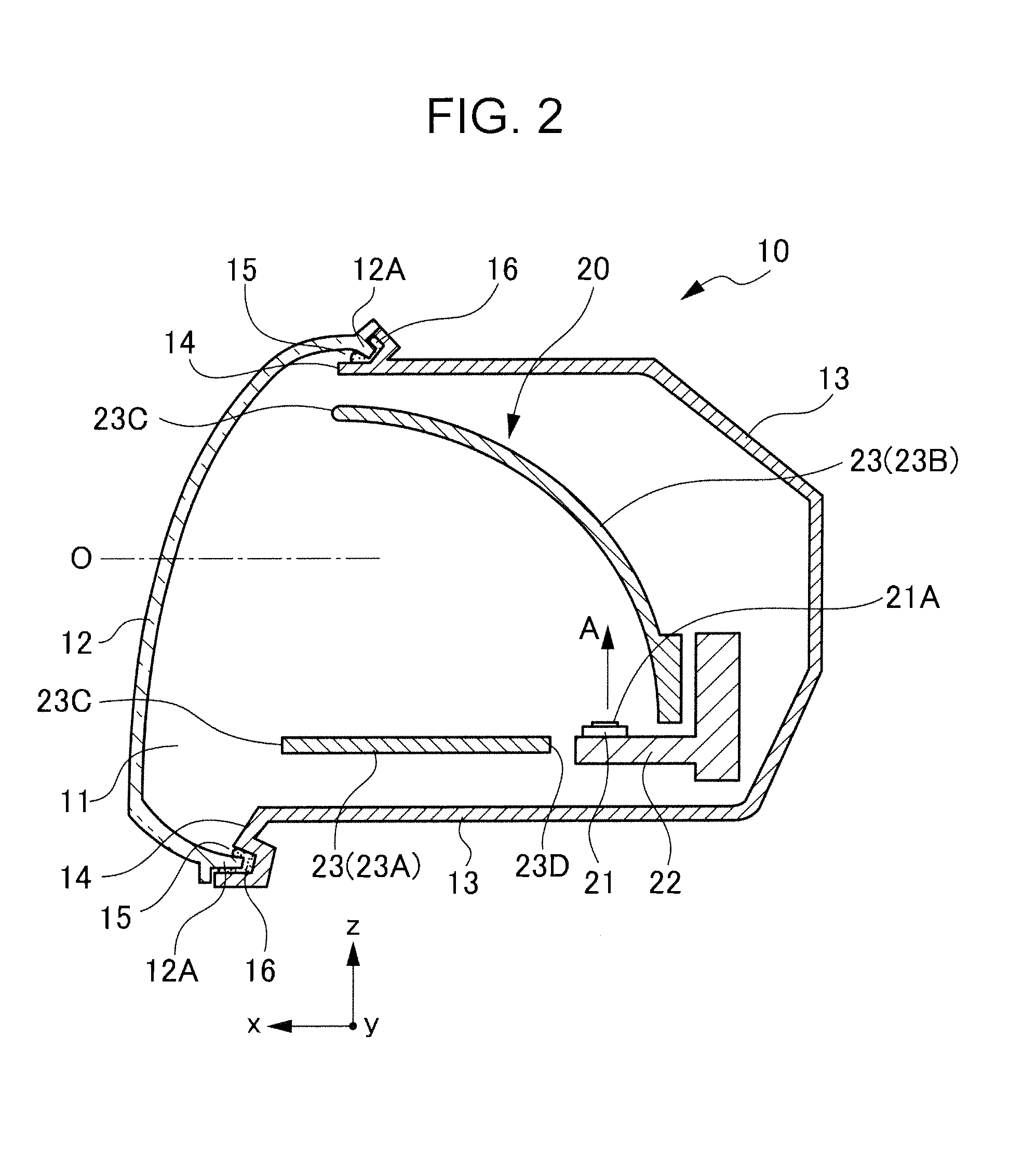
[0024]FIG. 2 is a sectional view showing schematics of a vehicle lighting device according to a first embodiment of the present invention. FIG. 2 shows a vehicle lighting device 10 made of a front lamp (a headlamp), for example. In FIG. 2, the x-direction, y-direction, and z-direction respectively indicate a forward direction, a widthwise direction, and a vertical direction, in a case where the vehicle lighting device 10 is mounted on a vehicle.
[0025]In FIG. 2, the vehicle lighting device 10 is a device in which a lamp room 11 thereof is defined by a front lens 12 and a housing 13. The front lens 12 is disposed on a front side of a vehicle (on the left side shown in the figure), and the housing 13 is disposed on a rear side of the vehicle (on the right side shown in the figure).
[0026]The housing 13 has an opening 14 on a front part of the vehicle, and in an opening edge of the opening, a groove portion 15 is formed in such a manner as to insert a peripheral edge portion 12A of the f...
second embodiment
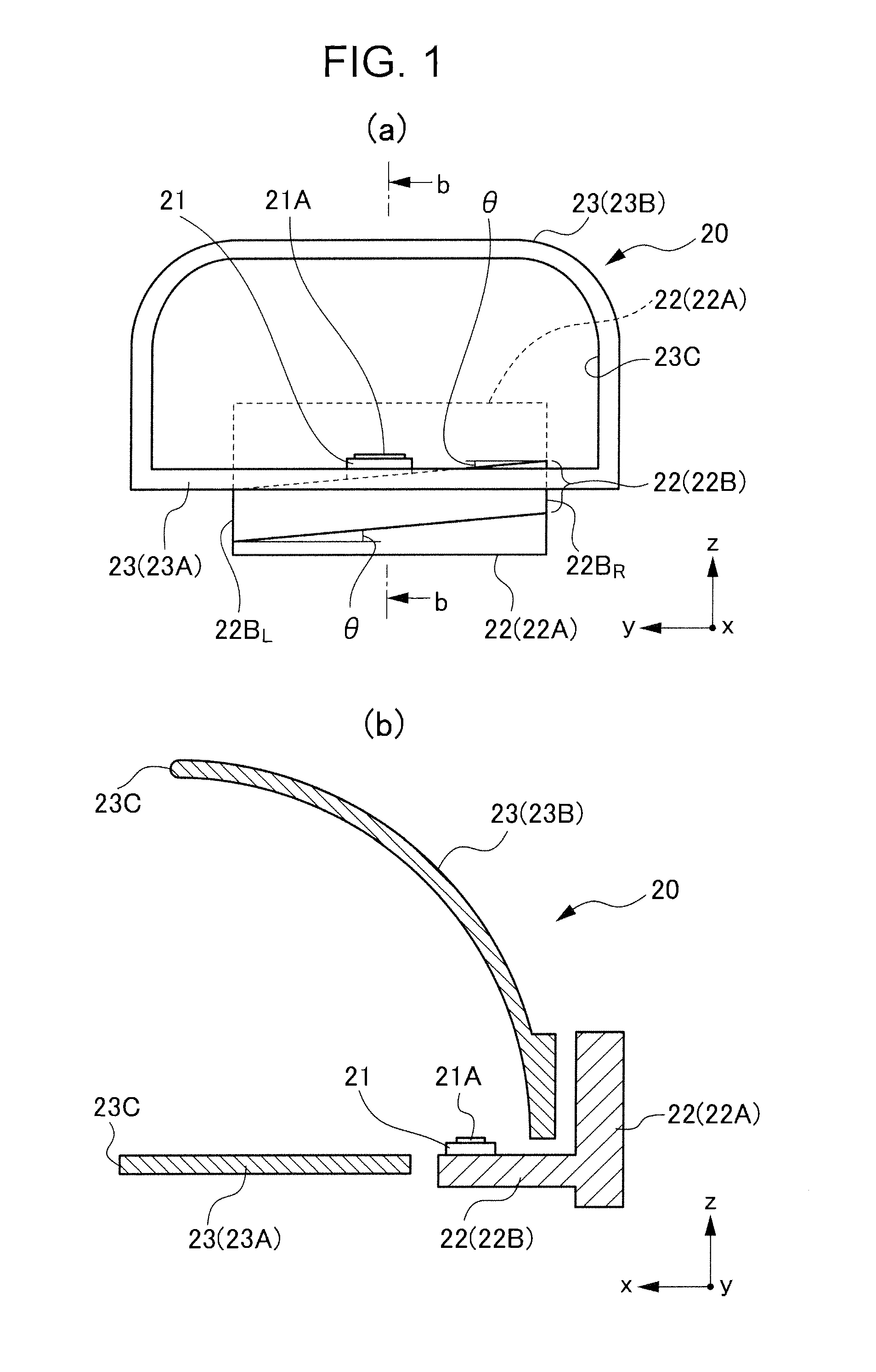
[0041]The light emitting diode 21 shown in the first embodiment is disposed on the light source mount member 22B so that the light emission surface 21A is substantially flush with the horizontal surface in the widthwise direction of the vehicle in a case where the vehicle lighting device 10 is mounted on the vehicle. However, without being limitative thereto, of course, as is the case with the light source mount member 22B, the light emitting diode 21 may be disposed on the light source mount member 22B so that the light emission surface 21A tilts with respect to the horizontal surface in the widthwise direction of the vehicle (the x-y plane in the figure). In this case, light from the light emitting diode can be emitted to the front lens side in a predetermined light distribution state by changing a design of a light reflection surface of a reflector. From the foregoing scope of work, it is needless to say that the light emitting diode 21 may be mounted to tilt in a forward / backwar...
third embodiment
[0042]While the heat sink 22 shown in the first embodiment has been described as a heat sink in which the heat sink main body 22A and the light source mount member 22B are integrally provided respectively, of course, these heat sink main body 22A and light source mount member 22B may be separately formed respectively, and for example, these elements may be configured to be combined with each other by means of screw or the like.
PUM
 Abstract
Description
Claims
Application Information
 - R&D
- Intellectual Property
- Life Sciences
- Materials
- Tech Scout
- Unparalleled Data Quality
- Higher Quality Content
- 60% Fewer Hallucinations
Browse by: Latest US Patents, China's latest patents, Technical Efficacy Thesaurus, Application Domain, Technology Topic, Popular Technical Reports.
© 2025 PatSnap. All rights reserved.Legal|Privacy policy|Modern Slavery Act Transparency Statement|Sitemap|About US| Contact US: help@patsnap.com


