
Agitation Apparatus with Interchangeable Module and Impact Protection Using Reactive Feedback Control

a technology of reactive feedback control and agitation apparatus, which is applied in the direction of rotary stirring mixer, transportation and packaging, mixing, etc., can solve the problems of mixing, resuspension, homogenization or disruption of the contents of the tube may crack or break, so as to reduce the noise observed by the user. , the effect of convenient and cost-effectiv

Active Publication Date: 2013-03-07
HART BRENDAN GEORGE +2
View PDF5 Cites 12 Cited by
  • Summary
  • Abstract
  • Description
  • Claims
  • Application Information

AI Technical Summary

Benefits of technology

The present invention provides a protective sleeve for tubes that allows them to be impacted without damage, and a removable module that can be used with different sized tubes or placement configurations. The module contains a rotatable hub shaft with strikers that can be adjusted based on the load, and the system can sense when a tube has broken and stop the apparatus from running. The invention also has the ability to adjust the impact speed based on the load. The module is placed inside a control enclosure, which provides a layer of sound isolation to reduce noise. The use of multiple interchangeable modules with a single control enclosure is convenient and cost-effective compared to multiple standalone apparatuses. The method of controlling the impact speed and detecting tube damage using electronics is efficient and effective.

Problems solved by technology

The impact of the strikers on the tubes induces turbulent motion of the contents, resulting in mixing, resuspension, homogenization or disruption of the tube contents.
Tubes made of plastic or another brittle material may crack or break on impact, splattering contents and risking cross-contamination of other tubes.
In addition, the cap on the tube may loosen or completely open.
If the tube is struck in a position that is too high or too low, momentum transfer between the striker and the tube may not be sufficient, or the tube may crack.
If the height of strikers on the axis / hub is non-adjustable, the striking technology can only be used with one tube size or shape.
In addition, the Sherman patent called for an upper and lower plate to hold the tubes in place, limiting the movement of the tubes and thus limiting the agitation of the tube contents.
Multiple models would inconvenience the user with significant extra cost and require extra laboratory space.
Keeping extra units in storage to save space would only increase time lost to equipment set up.
This increasing speed would increase the risk of additional tubes breaking.
Tubes with samples of larger mass would also create more resistance for the motor, and decreasing the prior art's effectiveness.
The prior art lacks a form of feedback to detect tubes breaking, and control the speed for a desired level of impact.
In addition, the prior art has no way to compensate for the mass or viscosity of the samples in the tubes
We have found that an issue experienced by the prior art was a build-up of heat within the tubes due to friction from direct impacts by the strikers.
Heat rising within samples can create adverse conditions for some methods of scientific analysis.
Additionally, we have found that impacts on tubes result in a very loud running volume.
The user may experience an uncomfortable level of noise, often times too loud to hold a normal conversation while in close proximity.
Covering the unit would reduce the noise but doing this would exacerbate heat build-up by restricting or limiting ambient air.

Method used


Image

  • Agitation Apparatus with Interchangeable Module and Impact Protection Using Reactive Feedback Control
  • Agitation Apparatus with Interchangeable Module and Impact Protection Using Reactive Feedback Control
  • Agitation Apparatus with Interchangeable Module and Impact Protection Using Reactive Feedback Control

Examples


first embodiment

FIGS. 1a-d, 2a-c and 3a-b

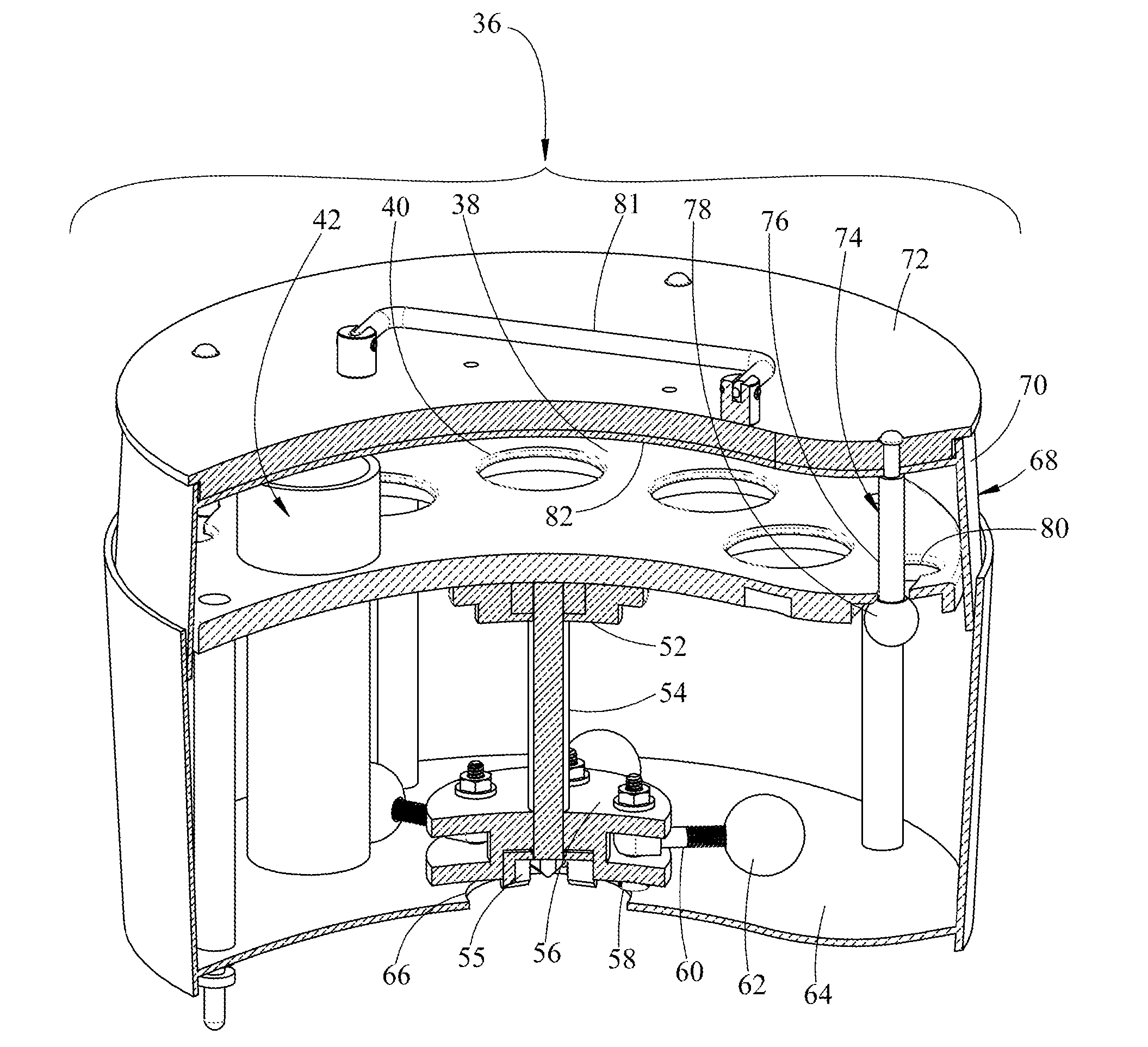
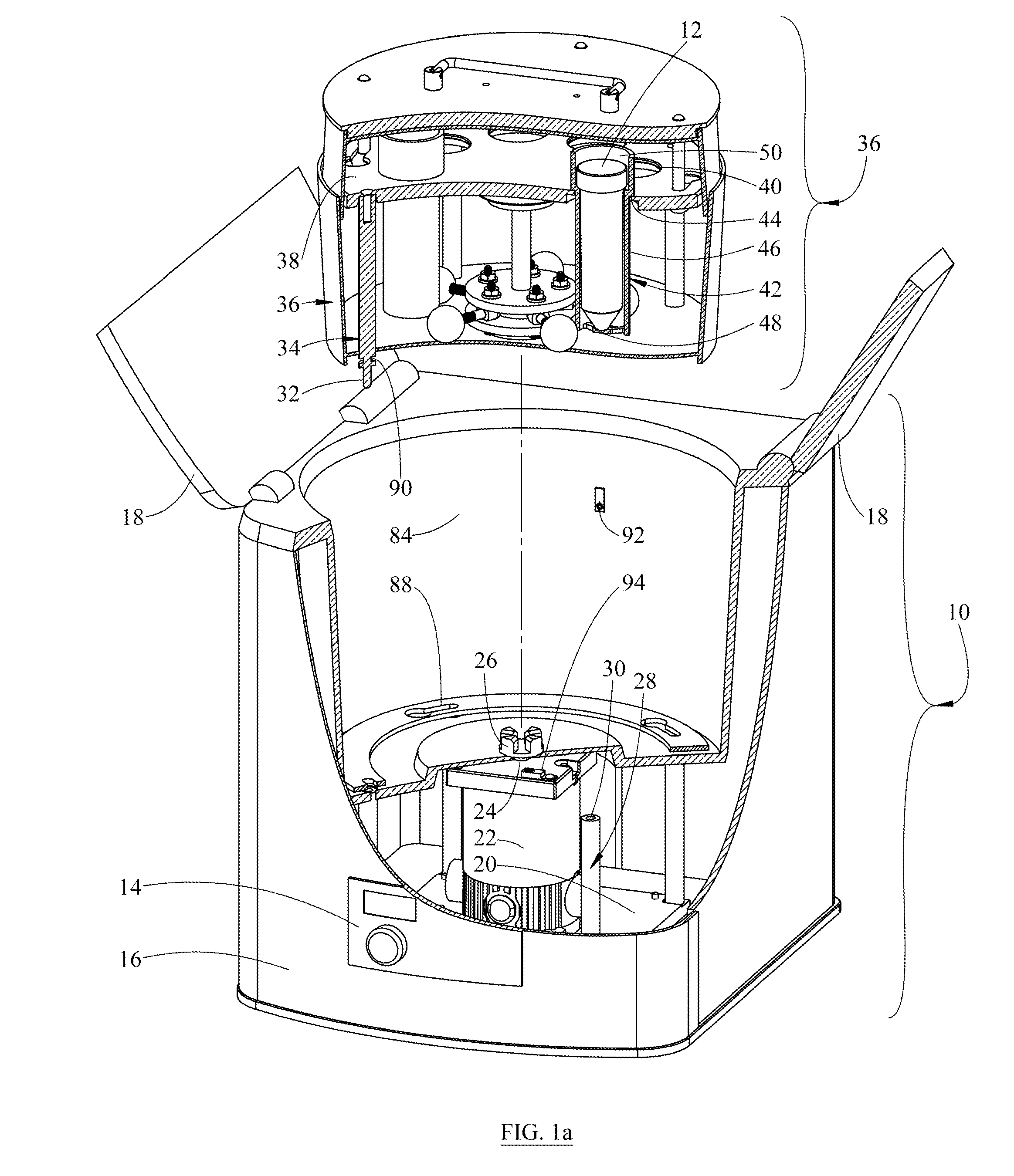
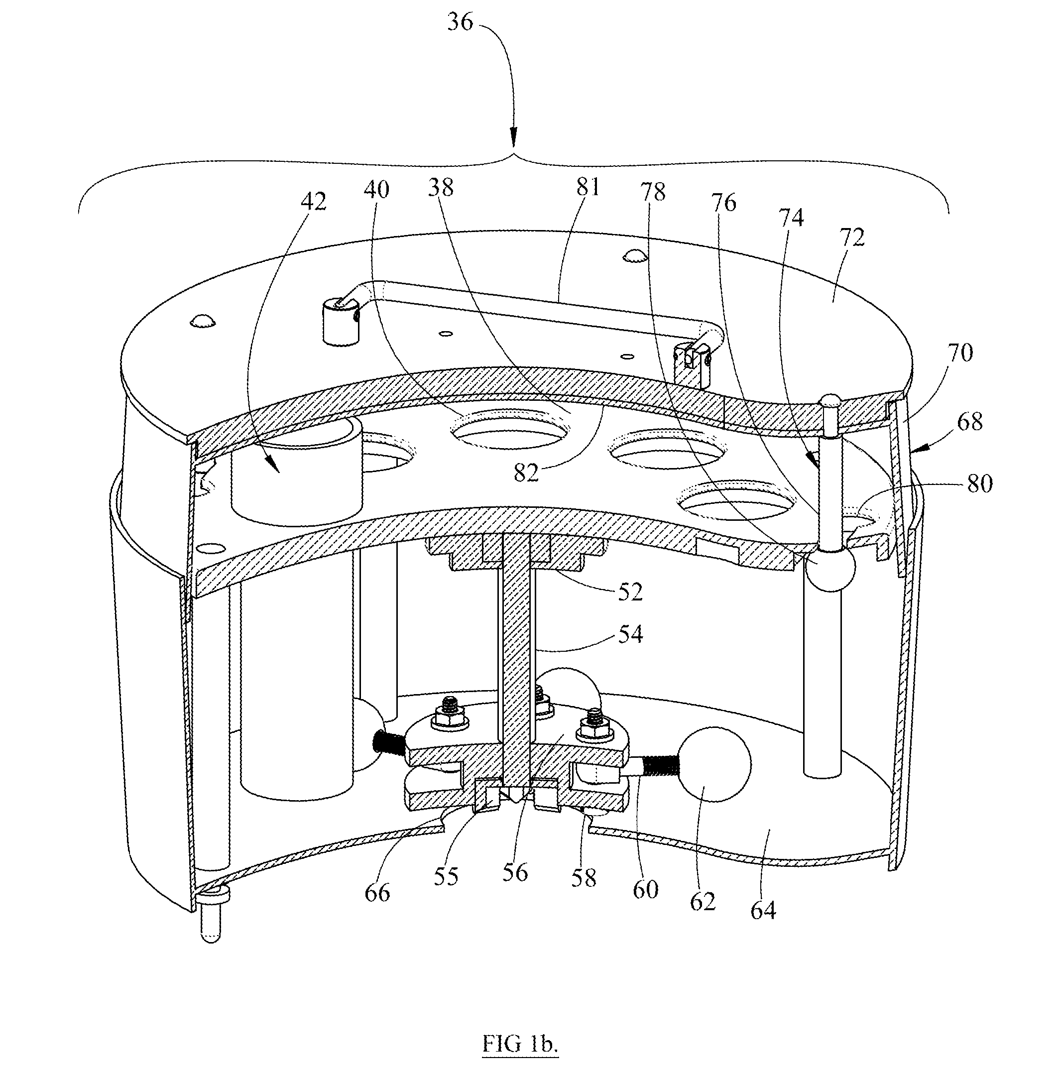
[0024]One embodiment of the present invention is illustrated in FIG. 1a-d, 2a-c and 3a-b. FIG. 1a shows an instrument or control enclosure 10 for impacting tubes 12; causing frequent oscillations and energetic movement for said tubes 12. The control enclosure 10 refers to several elements acting as a stationary base. The control enclosure 10, contains the electronics (not shown), and internal components. The main body of the control enclosure 10 is an outer housing 16. The front of the outer housing 16 has user controls or user interface 14. The top of the outer housing 16 has an outer lid or cover 18, which splits opening from the center and hinged on the top of the outer housing's 16 right and left sides.

[0025]Mounted to the inside of the outer housing 16 on the bottom face is a motor mounting plate 20. A variable speed electric motor 22 is affixed to the center of the motor mounting plate 20. A drive shaft 24 projects upward to a lower disconnecting coup...


PUM


Abstract

An apparatus for agitating materials contained in tubes, including cellular materials and tissues, to release their contents for scientific analysis. The apparatus includes a control enclosure containing a base and a motor, and an interchangeable module that connects to the motor. The interchangeable module includes a tube supporting structure and a rotatable hub connected to one or more strikers positioned to impact the tubes, resulting in agitation of tube contents. Interchangeable modules allow for different shapes and sizes of tubes to be used with a single control enclosure. The apparatus includes a means to measure the rotational velocity of the rotatable hub and a method for using the speed to determine the number of tubes in the apparatus, or the mass or volume of samples contained in tubes. The method accordingly adjusts the rotational velocity of the strikers allowing the tubes to receive consistent agitation independent of the number of tubes in the apparatus or mass or volume of samples within said tubes. The apparatus further includes protective sleeves for the tubes to prevent breakage, heat build-up from friction and tube caps opening due to rapid impact from strikers.

Description

BACKGROUNDPrior Art[0001]The following lists some prior art which presently appears relevant:U.S. PatentPatent NumberIssue DatePatentee5,769,5381998 Jun. 23Sherman6,281,0052001 Aug. 28Casal7,866,8782011 Jan. 11Howe7,874,7192011 Jan. 25Markle5,464,7731995 Nov. 7Melendez[0002]Disruption of cells and tissues is a common procedure carried out in biology laboratories to release nucleotides, proteins, virus, small molecules, chemicals, or whole cells for scientific analysis. It is often desirable to disrupt many samples simultaneously in individual tubes or containers to avoid cross contamination and to save time. A striking technology has been described to mechanically disrupt substances in tubes (U.S. Pat. No. 5,769,538 to Sherman). This technology is based on strikers that rotate around a hub or an axis and rapidly contact the tubes with contents inside. The impact of the strikers on the tubes induces turbulent motion of the contents, resulting in mixing, resuspension, homogenization o...

Claims


Application Information

Patent Timeline
Patent Type & Authority Applications(United States)
IPC IPC(8): B01F13/00B01L9/06
CPCB01F11/0275B01L9/06B01L2300/123B01L2200/085B01L2300/0803B01L2200/025B01F31/861B01F27/88B01F29/322
Inventor HART, BRENDAN GEORGEGLASGOW, IAN KEITHGRINNELL, DAVID
Owner HART BRENDAN GEORGE
Learn More