Fluid control device

a control device and fluid technology, applied in the direction of machines/engines, flexible member pumps, positive displacement liquid engines, etc., can solve the problems of poor temperature characteristics of the fluid pump, the limitation of miniaturizing the fluid pump having the conventional structure, and the fluid pump performance decreases, etc., to achieve a larger discharge flow rate, increase the effect of vibration, and increase the discharge pressur

Active Publication Date: 2013-03-07
MURATA MFG CO LTD
View PDF4 Cites 19 Cited by
  • Summary
  • Abstract
  • Description
  • Claims
  • Application Information

AI Technical Summary

Benefits of technology

[0047]According to this configuration, the movable portion vibrates with vibration of the actuator. For this reason, in the fluid control device, the amplitude of vibration is effectively increased. Thus, the fluid control device can achieve a higher discharge pressure and a larger discharge flow rate despite the small size and low profile design thereof.

Problems solved by technology

However, the performance of the fluid pump decreases as the fluid pump becomes smaller.
Therefore, there are limitations to miniaturizing the fluid pump having the conventional structure while maintaining the pump performance.
Therefore, a problem exists with the fluid pump 901 in which the pressure-flow rate characteristics of the fluid pump 901 will vary depending on changes in temperature.
In other words, the temperature characteristics of the fluid pump 901 are poor.

Method used


Image

  • Fluid control device
  • Fluid control device
  • Fluid control device

Examples


Embodiment Construction

[0059]Hereinafter, a piezoelectric pump 101 will be described according to a first preferred embodiment of the present invention.

[0060]FIG. 3 is an external perspective view of the piezoelectric pump 101 according to the first preferred embodiment of the present invention. FIG. 4 is an exploded perspective view of the piezoelectric pump 101 as shown in FIG. 3. FIG. 5 is a cross-sectional view of the piezoelectric pump 101 as shown in FIG. 3 taken along line T-T.

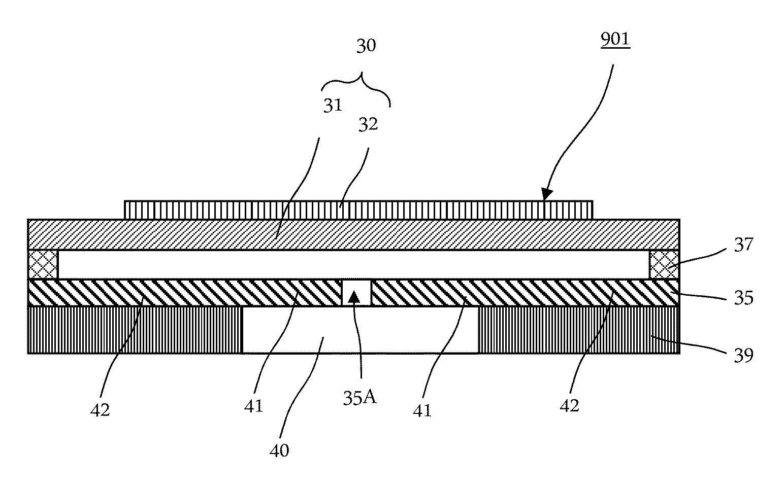
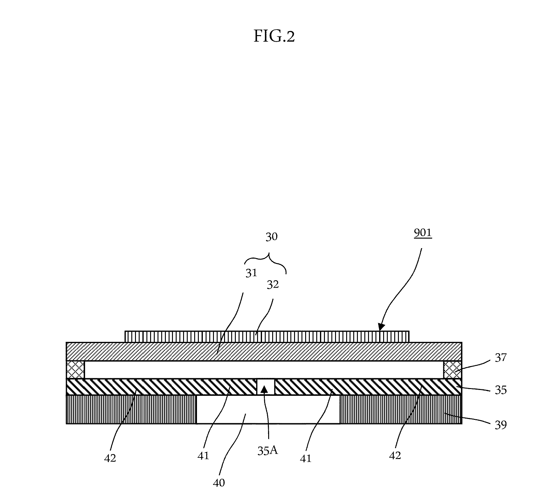
[0061]As shown in FIG. 3 to FIG. 5, the piezoelectric pump 101 preferably includes a cover plate 195, a base plate 191, a flexible plate 151, a vibrating plate unit 160, a piezoelectric element 142, a spacer 135, an electrode conducting plate 170, a spacer 130, and a lid portion 110. The piezoelectric pump 101 is provided with a structure in which the above components are layered in that order.

[0062]A vibrating plate 141 has an upper surface facing the lid portion 110, and a lower surface facing the flexible plate 151.

[0063]T...


PUM


Abstract

A fluid control device includes a vibrating plate unit, a driver, a flexible plate, and a base plate. The vibrating plate unit includes a vibrating plate including first and second main surfaces, and a frame plate surrounding the surrounding of the vibrating plate. The driver is bonded to the first or the second main surface of the vibrating plate and vibrates the vibrating plate. The flexible plate includes a hole provided therein, and is bonded to the frame plate so as to face the vibrating plate. The base plate is bonded to the main surface of the flexible plate on a side opposite to the vibrating plate. A size relationship between the coefficients of linear expansion of the material of the base plate and the frame plate is equal to a size relationship between the coefficients of linear expansion of the material of the vibrating plate and the driver.

Description

CROSS REFERENCE[0001]This non-provisional application claims priority under 35 U.S.C. §119(a) to Patent Application No. 2011-194429 filed in Japan on Sep. 6, 2011, the entire contents of which are hereby incorporated by reference.BACKGROUND OF THE INVENTION[0002]1. Field of the Invention[0003]The present invention relates to a fluid control device which performs fluid control.[0004]2. Description of the Related Art[0005]International Publication No. 2008 / 069264 discloses a conventional fluid pump (see FIGS. 1A to 1E). FIG. 1A to FIG. 1E show operations of the conventional fluid pump in a tertiary mode. The fluid pump, as shown in FIG. 1A, includes a pump body 10; a vibrating plate 20 in which the outer peripheral portion thereof is attached to the pump body 10; a piezoelectric element 23 attached to the central portion of the vibrating plate 20; a first opening 11 formed on a portion of the pump body 10 that faces the approximately central portion of the vibrating plate 20; and a se...

Claims


Application Information

Patent Timeline
Patent Type & Authority Applications(United States)
IPC IPC(8): F04B45/047
CPCF04B45/047F04B43/043
Inventor HIRATA, ATSUHIKOKODAMA, YUKIHARUOMORI, KENTAFUJISAKI, MASAAKI
Owner MURATA MFG CO LTD
Why Eureka
Try Eureka