Hydraulic circuit for transmission

A technology of hydraulic circuit and transmission, applied in the direction of components with teeth, transmission control, belt/chain/gear, etc., can solve the problems of vehicle starting delay, oil loss, time-consuming, etc., and achieve the effect of reducing the driving load

Active Publication Date: 2016-08-17
HONDA MOTOR CO LTD
View PDF6 Cites 5 Cited by
  • Summary
  • Abstract
  • Description
  • Claims
  • Application Information

AI Technical Summary

Problems solved by technology

[0007] However, if the vehicle is stopped for a long time, there is a problem that the oil inside the torque converter of the transmission is lost due to gravity, and it takes time until the torque converter is filled with oil when the engine is started next time even if the oil pump works , the torque converter cannot transmit the driving force, so the vehicle starts to delay

Method used


Image

  • Hydraulic circuit for transmission
  • Hydraulic circuit for transmission
  • Hydraulic circuit for transmission

Examples


no. 1 Embodiment approach

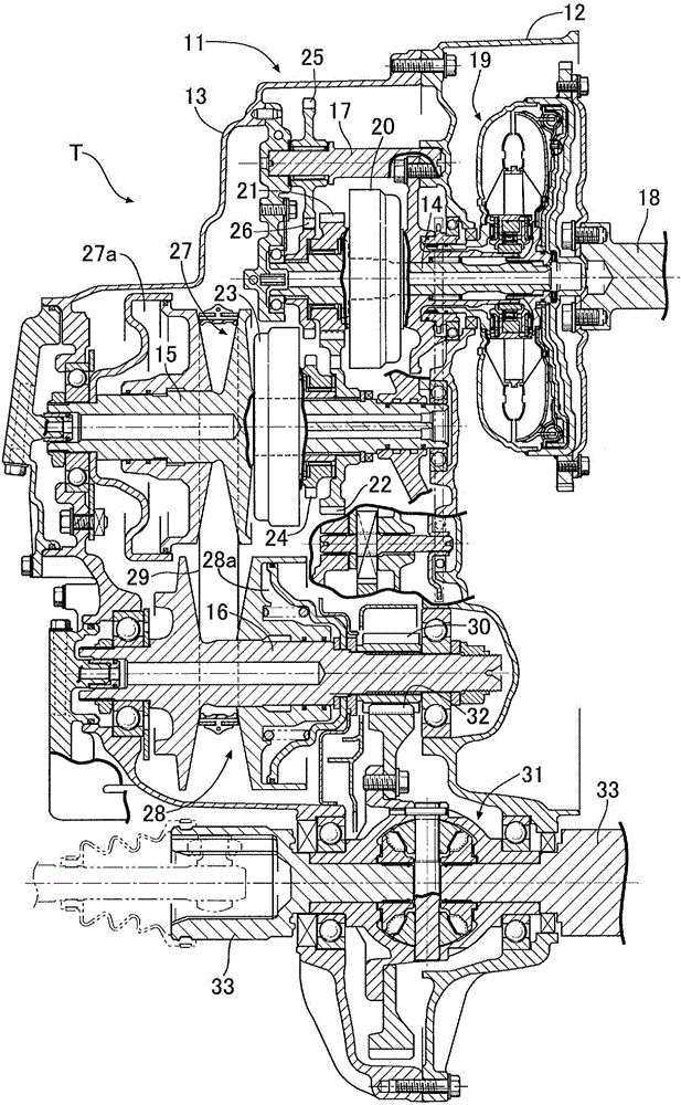
[0061] First, based on figure 1 The overall structure of the belt type continuously variable transmission T will be described. The transmission case 11 of the belt-type continuously variable transmission T includes a torque converter case 12 connected to an engine (not shown), a transmission case main body 13 connected to the torque converter case 12, an input shaft 14, and a drive pulley shaft 15. , the driven pulley shaft 16 and the idle shaft 17 are supported inside the transmission case 11 in parallel.

[0062] On the input shaft 14 connected to the crankshaft 18 of the engine via a torque converter 19, a forward drive gear 21 is supported in a relatively rotatable manner, and the forward drive gear 21 can be coupled to the input shaft 14 via a forward clutch 20. The forward drive gear 21 meshes with a forward driven driven gear 22 fixed to the drive pulley shaft 15 . The driven pulley shaft 15 is relatively rotatably supported with a reverse driven gear 24 that can be c...


PUM


Abstract

In a hydraulic circuit for a transmission, the circuit being provided with a main pump and a sub-pump, when the main pump (PM) and the sub-pump (PS) are driven by an engine (E) after being stopped for a long period of time, the oil pressure transmitted via a fifth oil path (L5) to a feedback port (P4) of a switching valve (V2) is insufficient because the internal pressure of a torque converter (19) is low, and because the connection between a first port (P5) and a second port (P6) of the switching valve (V2) is blocked, oil discharged by the sub-pump (PS) is not supplied to a lubricating system (48) via a sixth oil path (L6) and is supplied along the following route: second oil path (L2) - first port (P5) of switching valve (V2) - fourth oil path (L4) - first port (P8) and second port (P9) of second pressure regulating valve (V3) - torque converter (19). As a result, the interior of the torque converter (19) quickly fills with oil and drive force can be transmitted.

Description

technical field [0001] The present invention relates to a hydraulic circuit of a transmission, which includes a main pump and an auxiliary pump driven by a common drive source, supplies oil discharged from the main pump to a transmission control system, and supplies oil discharged from the auxiliary pump to a transmission control system. lubrication system. Background technique [0002] According to the following Patent Document 1, it is known that in the hydraulic circuit that supplies oil to the pulley oil chamber of the transmission, the torque converter, and the lubricating system through the main pump and the sub pump driven by the engine at the same time, when the vehicle suddenly accelerates or suddenly decelerates When the discharge flow rate of the main pump is insufficient and the hydraulic pressure of the torque converter or the lubricating system drops, the supply destination of the oil discharged from the sub pump is switched in the order of the pulley oil chamb...

Claims


Application Information

Patent Timeline
Patent Type & Authority Applications(China)
IPC IPC(8): F16H61/00
CPCF16H61/0206F16H61/0031F16H61/0025F16H57/0436F16H57/0446F16H61/0021F16H2061/0037
Inventor 市村泰之仲野茂司八下田智明
Owner HONDA MOTOR CO LTD
Why Eureka
Try Eureka