
Pump unit

A pump unit, fixed volume technology, applied in pump control, mechanical equipment, machine/engine, etc., can solve the problems of large-scale pump unit cost, high speed, high noise and vibration of pump unit, and achieves omission of wiring and simple operation. , the effect of preventing fluctuations in pressure and flow

Inactive Publication Date: 2005-08-24
DAIKIN IND LTD
View PDF0 Cites 3 Cited by
  • Summary
  • Abstract
  • Description
  • Claims
  • Application Information

AI Technical Summary

Problems solved by technology

However, if the above-mentioned high-torque motor is used, it will lead to problems of increasing the size and cost of the pump unit
In addition, if the small-capacity fixed-displacement pump is used, the rotation speed of the pump and the motor becomes too high during high-flow operation, so there is a problem of excessive noise and vibration of the pump unit.

Method used


Image

  • Pump unit
  • Pump unit
  • Pump unit

Examples


Embodiment Construction

[0023] Hereinafter, the present invention will be described in detail with reference to the illustrated embodiments.

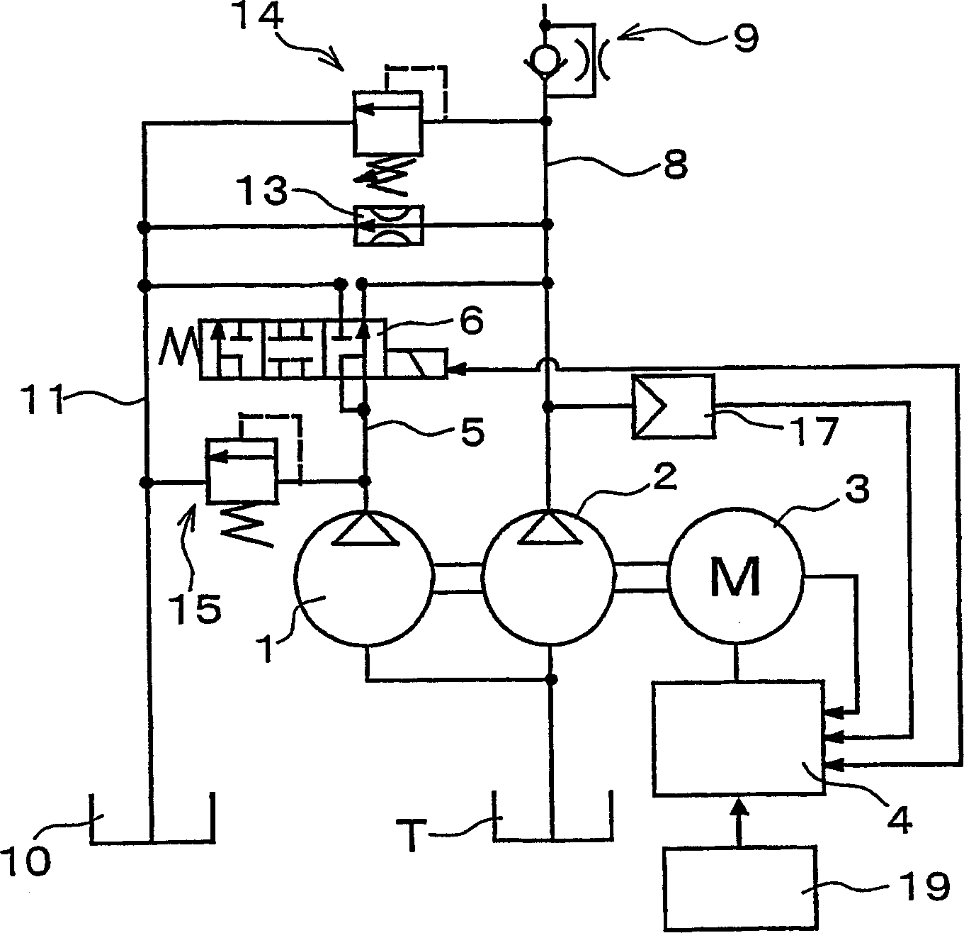
[0024] figure 1 It is a figure which shows the pump unit which concerns on embodiment of this invention. This pump unit is a pump unit that supplies the working fluid in the oil tank T to a hydraulic drive device such as a hydraulic cylinder (not shown). The pump unit has a first pump 1 as a large-capacity first fixed-displacement pump, and a second pump 2 as a small-capacity second fixed-displacement pump directly connected to the first pump 1 . The first pump 1 is composed of a 5.5cc / rev gear pump, and the second pump 2 is composed of a 3.5cc / rev gear pump. The first pump 1 and the second pump 2 are connected to a variable speed motor 3 , and the variable speed motor 3 is electrically connected to a control device 4 . The discharge passage 5 of the first pump is connected to a switching valve 6 , and can be switched to the discharge passage 8 of the seco...


PUM


Abstract

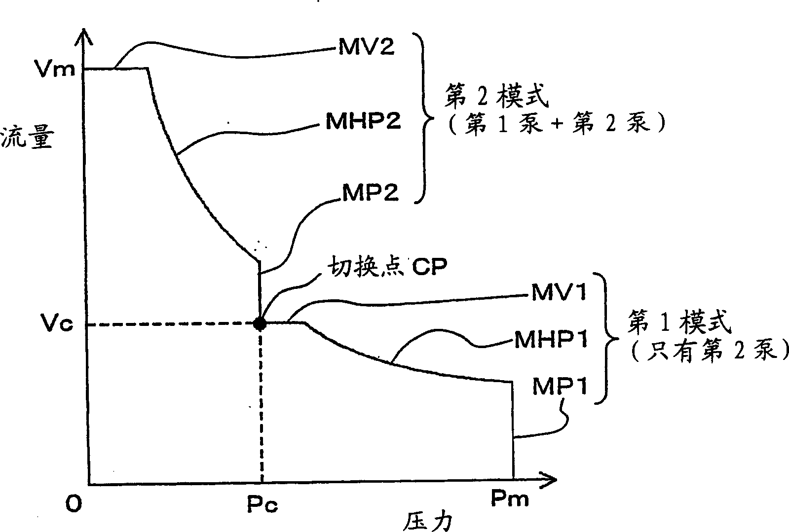
Provided is a pump unit capable of obtaining high discharging pressure by a motor having comparatively small torque, and decreasing noise / vibrations at the time of large flow operation. A first pump (1) made from a gear pump of a small capacity, and a second pump made from a gear pump of a large capacity are directly united by a variable speed motor (3) controlled in the number of revolutions by a control device (4). In a first mode. a discharge line (5) of the first pump is diverted from a discharging line (8) of the second pump, and the first pump is unloaded to carry out constant horsepower operation, thereby making a discharge fluid have high pressure by comparatively small torque. In a second mode, the discharging line (5) of the first pump is merged with the discharging line (8) of the second pump to carry out the constant horsepower operation, thereby discharging the large flow amount of the discharge fluid at a comparatively low number of revolutions. When the number of revolutions of the variable speed motor (3) is lower than a specified value, a switch valve (6) is switched from a merging state to a diverting state. When discharging pressure is lower than a specified value, the switch valve (6) is switched from the diverting state to the merging state.

Description

technical field [0001] The invention relates to pump units. Background technique [0002] As existing pump units such as Figure 4 shown. The pump unit has a fixed displacement pump 52 driven by a variable speed motor 51 with variable speed and a control unit 53 that controls the speed of the motor 51 by changing the frequency of the current supplied to the variable speed motor 51 . The control unit 53 receives the signal from the pressure sensor 54 that detects the pressure of the discharge path of the pump 52, and controls the speed of the pump 52 by controlling the speed of the variable speed motor 51, so that the pressure detected by the pressure sensor 54 The pressure value becomes a predetermined value. [0003] However, since the conventional pump unit drives a fixed displacement pump 52 with a variable speed motor 51, in order to increase the discharge pressure of the fixed displacement pump 52, it is necessary to use a large torque motor or a small capacity fixed ...

Claims


Application Information

Patent Timeline
Patent Type & Authority Applications(China)
IPC IPC(8): F04B49/00F04B49/06F04B49/08F04C14/02F04C14/06F04C14/08
CPCF04B49/065F04B49/08F04C2270/56F04C14/08F04C14/06F04B49/007F04C14/02F04B49/06F04B49/002
Inventor 堀内均越智良行中辻顺
Owner DAIKIN IND LTD
Learn More