Motor control device

a technology of motor control and control system, which is applied in the direction of control system, instruments, electrical equipment, etc., can solve the problems of inability to remove external disturbances, adverse effects on processing, and inability to maintain stability of control system, so as to improve control performance and ensure stability of control system

Inactive Publication Date: 2013-03-14
MITSUBISHI ELECTRIC CORP
View PDF29 Cites 8 Cited by
  • Summary
  • Abstract
  • Description
  • Claims
  • Application Information

AI Technical Summary

Benefits of technology

[0012]According to the motor control device of the present invention, by using each of the pieces of information including the elastic constant of the target, the information regarding the reaction force of the motor torque or the thrust, generated with the application of the dynamic physical quantity from the mechanical load to the target, the information of the transfer characteristic of the motor torque or the thrust to the motor speed, the motor position, or the motor acceleration, the information of the a control law of the spe

Problems solved by technology

When the parameter is too large, the stability of a control system is impaired, resulting in instability of the control system or occurrence of a vibration phenomenon in which a high-frequency micro-vibration is superimposed on the pressure applied to the pressurized target.
By the transmission of the micro-vibration generated by the vibration phenomenon to the work piece or the like, the result of

Method used


Image

  • Motor control device
  • Motor control device
  • Motor control device

Examples


first embodiment

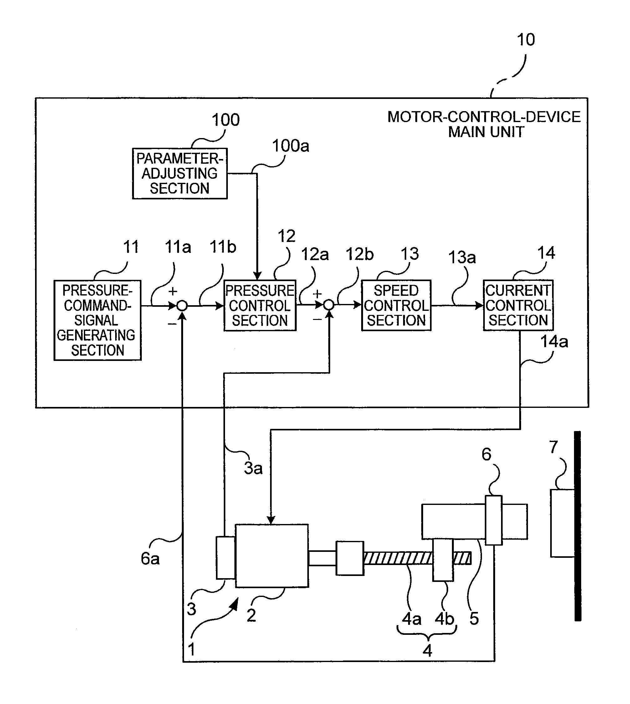
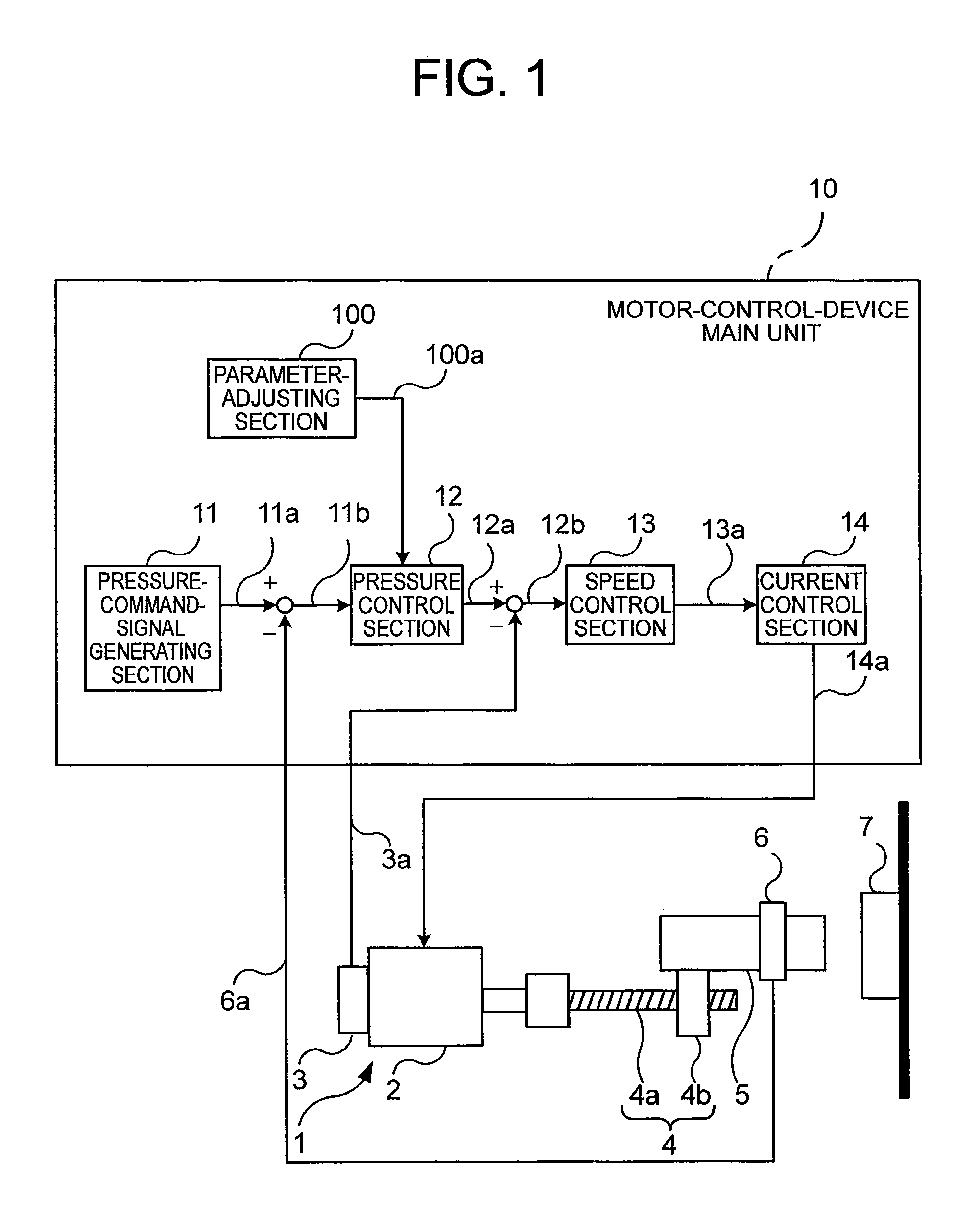
[0041]FIG. 1 is a block diagram illustrating a motor control device according to a first embodiment of the present invention.

[0042]In FIG. 1, a processing device 1 includes an electric mechanism 4 including a rotary type motor (pressurizing motor) 2 and an encoder 3, a mechanical load (pressing member) 5, and a pressure detector 6.

[0043]The encoder 3 is speed detecting means for generating a motor-speed detection signal 3a in accordance with a rotating speed of the motor 2. The electric mechanism 4 is a feed-screw mechanism for converting rotational movement into translational movement, and includes a screw 4a and a ball-screw nut 4b. The screw 4a is rotated by the motor 2 in a circumferential direction thereof. The ball-screw nut 4b is displaced in an axial direction of the screw 4a with the rotation of the screw 4a.

[0044]The mechanical load 5 is mounted to the ball-screw nut 4b. A distal end of the mechanical load 5 is opposed to the pressurized target 7 (target). The mechanical ...

second embodiment

[0114]In the first embodiment, the case where the speed control is provided as the minor loop of the pressure control has been described. On the other hand, even in the case where position control is provided as the minor loop, that is, the pressure control section 12 outputs a signal having a dimension of position such as a position command signal, the control can be performed in the same manner as in the first embodiment. Therefore, the case where the position control is provided as the minor loop described above is described in a second embodiment.

[0115]FIG. 11 is a block diagram illustrating a motor control device according to the second embodiment. In FIG. 11, a configuration of a motor-control-device main unit 10 of the second embodiment is the same as that of the motor-control-device main unit 10 of the first embodiment except that a position control section 15 is further provided and a parameter-adjusting section 100 uses information regarding the position control. An encode...

third embodiment

[0135]The case where the speed control is provided as the minor loop of the pressure control has been described in the first embodiment, and the case where the position control is provided as the minor loop of the pressure control has been described in the second embodiment. However, even with a configuration in which the output of the pressure control section 12 directly becomes the torque of the motor without providing the minor loop, the control can be performed in the same manner as in the first and second embodiments. In the third embodiment, the above-mentioned configuration without the minor loop is described.

[0136]FIG. 15 is a block diagram illustrating a motor control device according to the third embodiment of the present invention. In FIG. 15, a configuration of a motor-control-device main unit 10 of the third embodiment is the same as the configuration of the motor-control-device main unit 10 of the first embodiment except that the speed control section 13 is omitted. He...


PUM


Abstract

A motor-control-device main unit includes a pressure-command-signal generating section, a pressure control section, a speed control section, a current control section, and a parameter-adjusting section. With respect to a parameter for a control computation by the pressure control section, the parameter-adjusting section includes an information-acquiring section and a parameter-calculating section. The information-acquiring section acquires, from an exterior, each of pieces of information including an elastic constant of a pressurized target, a reaction-force constant indicating information of a reaction force, a transfer characteristic from a motor torque to a motor speed, and parameters of the speed control section. The information-acquiring section previously acquires information of a control law of the speed control unit. The parameter-calculating section calculates a parameter for the pressure control section based on the information acquired by the information-acquiring section.

Description

TECHNICAL FIELD[0001]The present invention relates to a motor control device which controls driving of a motor for pressing a mechanical load against a target.BACKGROUND ART[0002]In various types of molding machines such as injection-molding machines and press-molding machines and processing apparatus such as bonding machines (industrial machines and processing machines), an electric mechanism (mechanical driving section) is driven by a motor to apply a pressure to a pressurized target. In the processing apparatus described above, an actual pressure value, which is a pressure value obtained when a mechanical load is pressed against a molding material or a work piece which is the pressurized target, is detected as a pressure detection value. Based on the pressure detection value and a pressure command value, a pressure control computation defined by a parameter is performed. The parameter as used herein is a parameter such as a gain in the pressure control computation.[0003]It is nec...

Claims


Application Information

Patent Timeline
IPC IPC(8): H02P29/00
CPCB30B15/14B30B15/0094
Inventor UEDA, KOICHIROIKEDA, HIDETOSHI
Owner MITSUBISHI ELECTRIC CORP
Why Eureka
Try Eureka