
Power supply apparatus

a power supply and apparatus technology, applied in the direction of battery/fuel cell control arrangement, safety/protection circuit, instruments, etc., can solve the problems of inability to drive by the motor, vehicle to drive when the fuse is blown, and inability to supply electric power to a motor, so as to prevent overcharge or overdischarge, prevent overcharging or overcharging, and accurately determine the

Inactive Publication Date: 2013-03-14
SANYO ELECTRIC CO LTD
View PDF5 Cites 12 Cited by
  • Summary
  • Abstract
  • Description
  • Claims
  • Application Information

AI Technical Summary

Benefits of technology

The present invention relates to a power supply apparatus for vehicles. The apparatus includes a drive battery, a fuse, and a voltage detection circuit. The voltage detection circuit detects the voltage of a battery unit by dividing the voltage at a resistance voltage dividing circuit with a line connected to the fuse as a ground line. The blowout detection circuit detects a blowout of the fuse based on the voltage detected at the voltage detection circuit. The blowout detection circuit determines that the fuse is blown when the detected voltage of a battery unit connected to the fuse falls within an abnormal range. This prevents false determination of the fuse blowout and allows the vehicle to safely drive. The power supply apparatus detects voltages of multiple battery units to prevent overcharging or overdischarging and ensure correct and reliable detection of the fuse blowout.

Problems solved by technology

Since the power supply apparatus for a vehicle has the fuse connected in series with the battery, electric power cannot be supplied to a motor causing the vehicle to drive when the fuse is blown.
Blowing the fuse therefore leads to an inability to drive by the motor.

Method used


Image

  • Power supply apparatus
  • Power supply apparatus
  • Power supply apparatus

Examples


Embodiment Construction

[0025]Hereinafter, an embodiment of the present invention will be described with reference to the drawings. The embodiment described below is deemed to be merely illustrative of a power supply apparatus for giving a concrete form to the technical idea of the present invention, and therefore, the present invention is not limited to the power supply apparatus described below. Further, in the description, reference numerals corresponding to components described in the embodiment are assigned to components described in “Claims” and “Solution to Problem” for the sake of better understanding the claims. However, the reference numerals do not limit the component described in the claims to the components described in the embodiment.

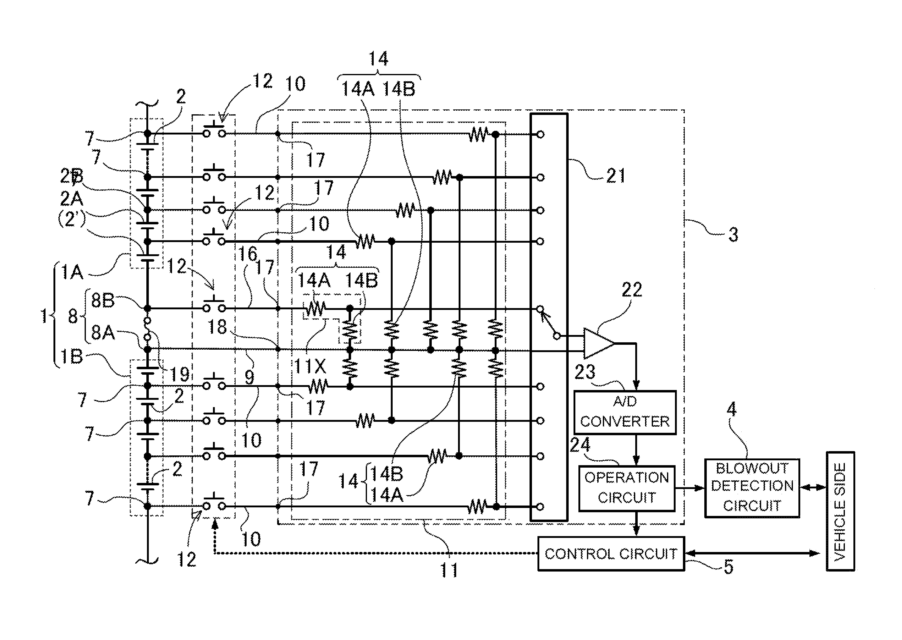
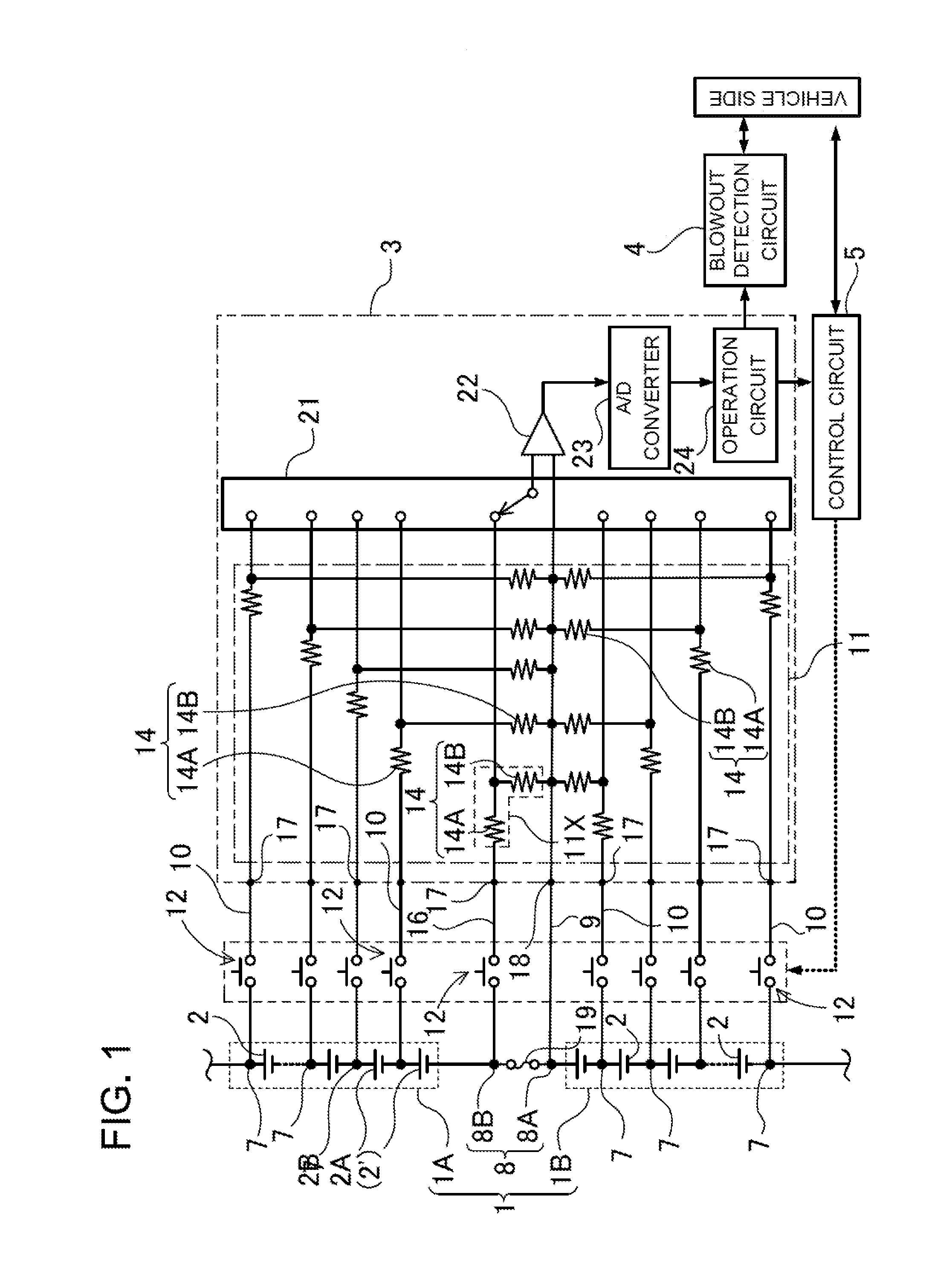
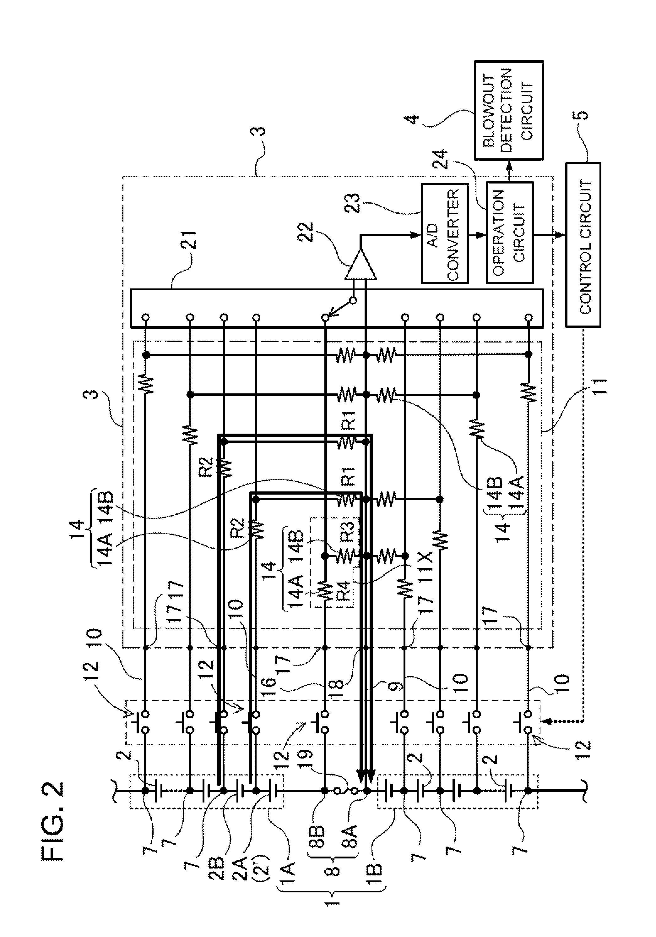
[0026]A power supply apparatus for a vehicle in FIG. 1 includes: a drive battery 1 having a plurality of battery units 2 connected in series; a fuse 19 connected in series with the drive battery 1; a voltage detection circuit 3 detecting a voltage of each battery...


PUM


Abstract

[Problem to be Solved] To prevent false determination of a fuse blowout with a fuse not blown by certainly detecting the fuse blowout.[Solution] A power supply apparatus includes: a drive battery (1) having a plurality of battery units (2) connected in series; a fuse (19) connected in series with the drive battery (1); a voltage detection circuit (3) detecting a voltage of the battery unit (2) by dividing the voltage at a resistance voltage dividing circuit (11) with a line connected to one end of the fuse (19) as a ground line; and a blowout detection circuit (4) detecting a blowout of the fuse (19) based on the voltage detected at the voltage detection circuit (3). The blowout detection circuit (4) determines that the fuse is blown when a detected voltage of the battery unit (2) connected to a fuse (19) side with respect to the ground line falls within an abnormal range. Further, in the power supply apparatus, the blowout detection circuit (4) determines that the fuse is blown when detected voltages of a plurality of battery units (2) fall within the abnormal range.

Description

TECHNICAL FIELD [0001]The present invention relates to a power supply apparatus mounted on, for example, a hybrid automobile, an electric automobile, or the like for supplying electric power to a motor causing a vehicle to drive and, more particularly, to a power supply apparatus having a circuit determining whether or not a fuse connected in series with a battery is blown.BACKGROUND ART [0002]A power supply apparatus for a vehicle including a battery has a fuse connected in series with the battery. An extraordinarily large current is blocked by blowing the fuse due to an overcurrent of the battery. The fuse is blown by heat generation thereof. Therefore, like a protection circuit including an electronic circuit, it can be avoided that a current cannot be blocked due to a circuit failure or a mechanism failure, thereby being able to stably block the overcurrent of the battery.[0003]Since the power supply apparatus for a vehicle has the fuse connected in series with the battery, elec...

Claims


Application Information

Patent Timeline
Patent Type & Authority Applications(United States)
IPC IPC(8): G01R31/02G01R31/74
CPCB60L3/0046B60L3/04B60L11/1803B60L11/1861B60L2240/547B60L2250/16H02J7/0031Y02T10/7005Y02T10/7011Y02T10/7044Y02T10/705B60L11/1859G01R31/07B60L50/51B60L58/14B60L58/15G01R31/74B60L58/18Y02T10/70H02J7/00
Inventor NAKAJIMA, KAORUNISHIMURA, MASATO
Owner SANYO ELECTRIC CO LTD
Learn More