Structure of windshield wiper

a windshield wiper and blade technology, applied in the field of windshield wiper structure, can solve the problems of increased inventory cost, troublesome automobile owners to replace and mount the windshield wiper blade assembly, etc., and achieve the effects of improving the structure reducing manufacturing costs, and expanding the applicability of the windshield wiper blad

Inactive Publication Date: 2013-03-21
FU GANG CO LTD
View PDF6 Cites 36 Cited by
  • Summary
  • Abstract
  • Description
  • Claims
  • Application Information

AI Technical Summary

Benefits of technology

[0003]The primary objective of the present invention is to provide an improved structure of windshield wiper, wherein a windshield wiper blade assembly is made coupleable with various styles of windshield wiper arm through replacement or exchange of various adaptors so that the windshield wiper blade assembly may be adaptively used with different models of automobile to provide an effect of reduction of manufacturing costs.
[0004]The improved structure of windshield wiper according to the present invention comprises a wiper blade assembly, a retainer, and a plurality of adaptors that is selectively and exchangeably mountable to the retainer. The retainer forms a mounting hole in a top of a front end portion and has a mounting bar rearward of the mounting hole and has a rear end portion forming a lower step section, which includes an engagement slot and an engagement rib respectively formed in front and rear sections of each side face thereof. The adaptors are of different structures. The retainer is coupled to the wiper blade assembly, or alternatively, the adaptors are selectively attached to the retainer, so that windshield wiper arms of different styles may selectively fit to the retainer or the adaptors to thereby expand the applicability of the windshield wiper blade.

Problems solved by technology

Thus, the retainer is only useful for one or several specific models of automobile and different models of automobile need different retainers.
This causes troubles for an automobile owner to replace and mount windshield wiper blade assembly.
Further, due to the wide diverse of windshield wiper products, manufacturers also need to spend additional effort in assembling and manufacturing the windshield wiper blade assemblies and also the inventory cost is increased.

Method used


Image

  • Structure of windshield wiper
  • Structure of windshield wiper
  • Structure of windshield wiper

Examples


Embodiment Construction

[0015]The following descriptions are exemplary embodiments only, and are not intended to limit the scope, applicability or configuration of the invention in any way. Rather, the following description provides a convenient illustration for implementing exemplary embodiments of the invention. Various changes to the described embodiments may be made in the function and arrangement of the elements described without departing from the scope of the invention as set forth in the appended claims.

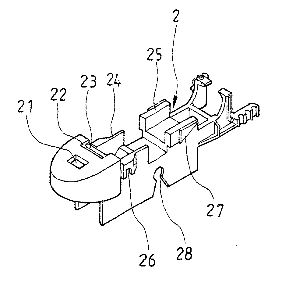
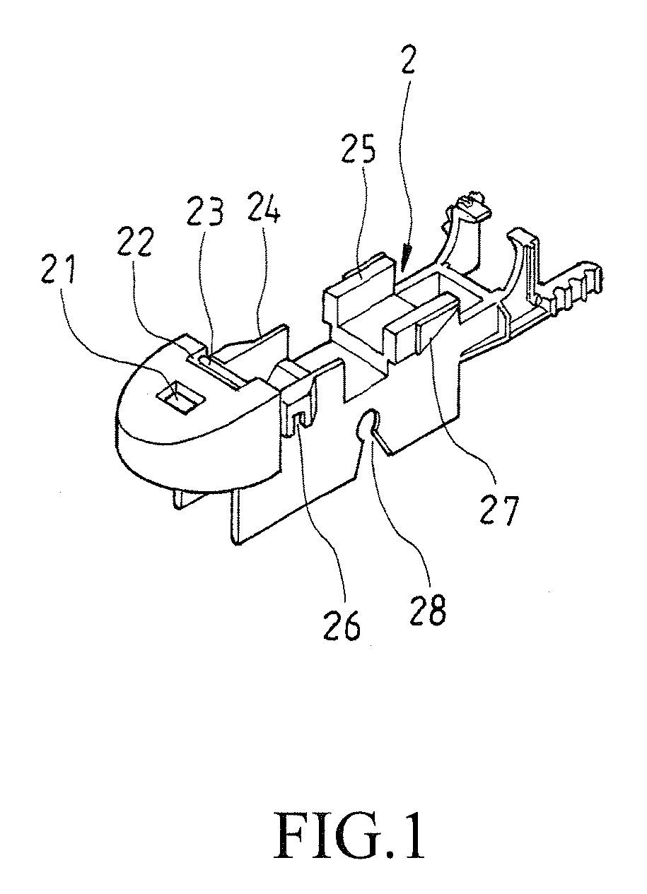
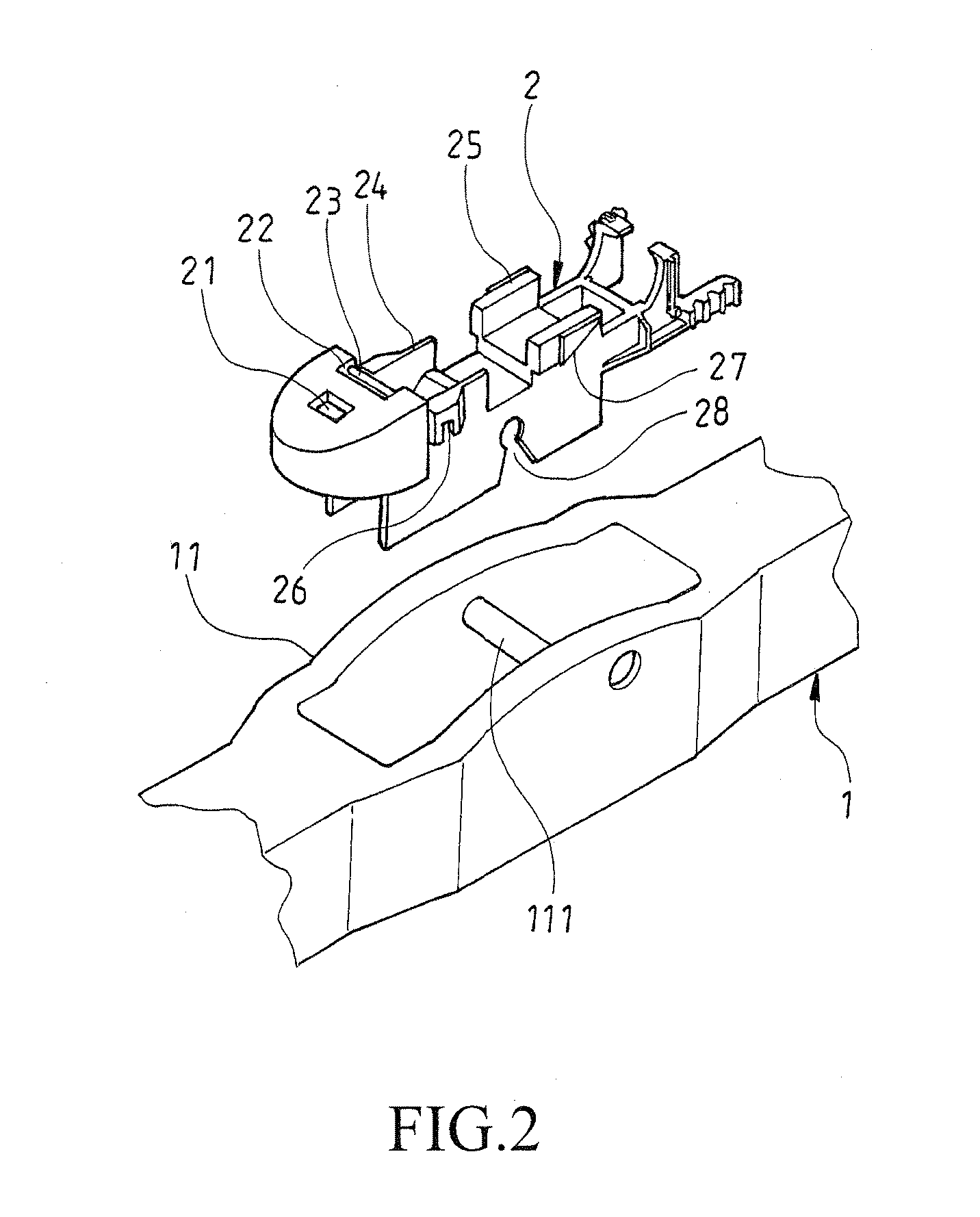
[0016]Referring to FIGS. 1 and 2, which are perspective views respectively showing a retainer according to the present invention and demonstrating mounting the retainer to a wiper blade assembly, as shown in these drawings, the present invention comprises a wiper blade assembly 1 and the retainer 2. The wiper blade assembly 1 has a central portion forming a positioning section 11 and the positioning section 11 comprises a coupling bar 111 fixed at a central portion thereof.

[0017]The retainer 2 is in...


PUM


Abstract

An improved structure of windshield wiper includes a wiper blade assembly, a retainer, and a plurality of adaptors that is selectively and exchangeably mountable to the retainer. The retainer forms a mounting hole in a top of a front end portion and has a mounting bar rearward of the mounting hole and has a rear end portion forming a lower step section, which includes an engagement slot and an engagement rib respectively formed in front and rear sections of each side face thereof The adaptors are of different structures. The retainer is coupled to the wiper blade assembly, or alternatively, the adaptors are selectively attached to the retainer, so that windshield wiper arms of different styles may selectively fit to the retainer or the adaptors to thereby expand the applicability of the windshield wiper blade.

Description

TECHNICAL FIELD OF THE INVENTION[0001]The present invention generally relates to an improved structure of windshield wiper, and more particularly to an improved structure of windshield wiper that comprises an adaptor for selectively mating and retaining wiper arms of different styles so as to allow windshield wiper blade to adapt to windshield wiper systems of different models of automobile.DESCRIPTION OF THE PRIOR ART[0002]A conventional way of coupling between a windshield wiper blade assembly and a windshield wiper arm is to provide a positioning section in around the center of the windshield wiper blade assembly for receiving a retainer to mount thereto so that the windshield wiper blade assembly may be coupled to a windshield wiper arm with the retainer. There are a variety of types and models of automobiles available in the market and the conventional retainer must be used in combination with a fitting member. Thus, the retainer is only useful for one or several specific model...

Claims


Application Information

Patent Timeline
Patent Type & Authority Applications(United States)
IPC IPC(8): B60S1/40
CPCB60S1/4003B60S1/4048B60S1/3801B60S1/4083B60S2001/409B60S1/4067
Inventor CHIANG, MIN-HENG
Owner FU GANG CO LTD
Why Eureka
Try Eureka