Oil sensor

a technology of oil sensor and lubricant, which is applied in the direction of liquid/fluent solid measurement, machines/engines, instruments, etc., can solve the problems of mass reduction and/or size, and achieve the effect of reducing the size and/or weight of components

Active Publication Date: 2013-03-21
ROLLS ROYCE PLC
View PDF1 Cites 26 Cited by
  • Summary
  • Abstract
  • Description
  • Claims
  • Application Information

AI Technical Summary

Benefits of technology

[0011]Typically in an engine, such as a gas turbine engine, it is important to minimize the size and/or weight of components. As such

Problems solved by technology

This may result in reduced mass and/or size, for example compared with a system in wh

Method used


Image

  • Oil sensor
  • Oil sensor
  • Oil sensor

Examples


Embodiment Construction

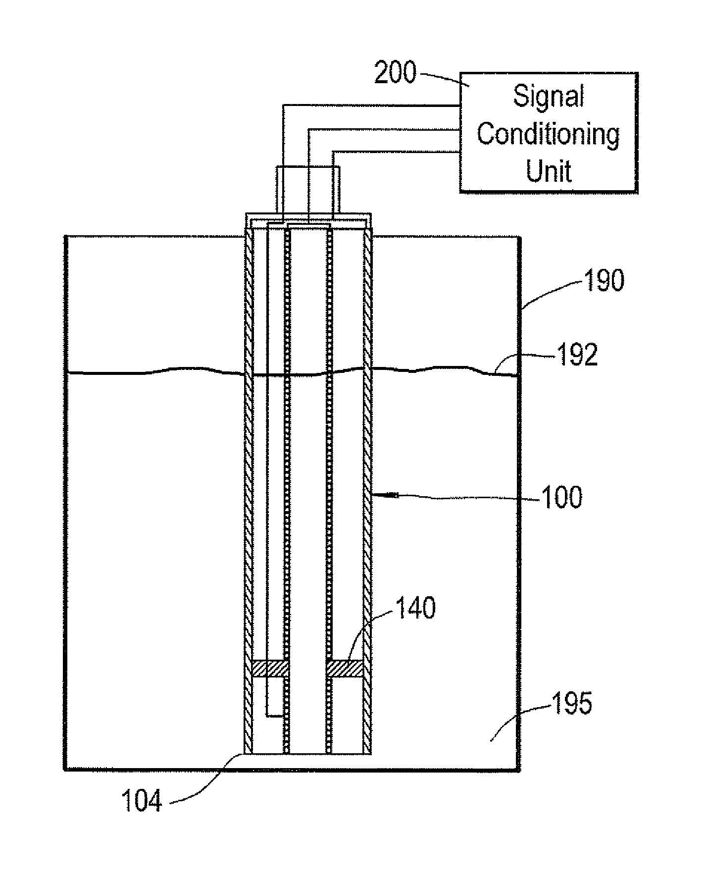
[0049]A typical engine includes a lubrication system. The lubrication system may provide lubricants, such as oil-based and / or synthetic-based lubricants to a number of different parts of the engine. Indeed, where reference is made herein to oil, it will be appreciated that this means any suitable fluid, such as any lubricant. The terms oil and lubricant are interchangeable herein.

[0050]The lubrication system may provide a lubricant to reduce the friction between parts which, in use, may move relative to each other and may rub against each other. This may help to improve performance and / or life of components within the engine. Such lubrication systems may be provided to any type of engine, for example internal combustion engines and gas turbine engines. If the type and / or amount (for example mass flow rate) of oil provided to particular parts of the engine is outside design specification, this may lead to increased wear and / or friction, which may lead to reduced life and / or performan...


PUM


Abstract

A system and method for measuring oil level and quality is provided. The system and method uses an alternating current (AC) to determine oil level, and a lower frequency alternating current, or a direct current (DC), to measure oil quality. The system may comprise a single sensor that is used to measure both oil quality (by providing the lower frequency alternating current or direct current) and oil level (by providing the higher frequency alternating current). Using the lower frequency AC, or DC, enables the resistance of the oil to be determined, which gives an accurate indication of the oil quality.

Description

CROSS-REFERENCE TO RELATED APPLICATIONS[0001]This application is based upon and claims the benefit of priority from British Patent Application Number filed 1116173.4 filed 20 Sep. 2011, the entire contents of which are incorporated by reference.BACKGROUND OF THE INVENTION[0002]1. Field of the Invention[0003]The present invention relates to a method and apparatus for monitoring lubricants in an engine. In particular, the present invention relates to monitoring the level and quality of a lubricant, such as oil, in an engine.[0004]During use, engines, such as gas turbine engines, require lubrication. For example, lubrication may be required to reduce the wear of internal parts that move relative to each other and / or to reduce the friction between such components. Typically, therefore, an engine is provided with a lubrication system, which may comprise one or more pumps and ducts to deliver a lubricant to the desired position in the engine.[0005]Any suitable lubricant may be used, such ...

Claims


Application Information

Patent Timeline
IPC IPC(8): G01F23/26
CPCG01F23/263G01F23/266G01N27/028G01N33/2888G01F23/268
Inventor SINHA, KARN R.DAVIS, NICHOLAS P.
Owner ROLLS ROYCE PLC
Why Eureka
Try Eureka