Hybrid hydraulic drive system architecture

a hydraulic drive system and hybrid technology, applied in mechanical equipment, transportation and packaging, gearing, etc., can solve the problems of increasing the cost of fuel consumption, wasting energy during frequent braking, and the current hydraulic drive system is not as effective in improving fuel economy. , to achieve the effect of reducing energy loss

Inactive Publication Date: 2013-03-21
EATON CORP
View PDF9 Cites 43 Cited by
  • Summary
  • Abstract
  • Description
  • Claims
  • Application Information

AI Technical Summary

Problems solved by technology

Unfortunately, these alternative drivetrain systems currently suffer from several limitations and, for all practical purposes, are still under development However, hybrid hydraulic and hybrid electric drivetrains have found success, particularly in vehicle applications with a lot of starting and stopping.
In conventional drive systems, frequent braking wastes a significant amount of energy as heat, especially in larger vehicles.
However, current hydraulic drive systems are not as effective in improving fuel economy in applications where the vehicle operates at a consistent, steady-state speed.
However, the performance of a parallel hybrid system is also inherently limited by its dependence on a mechanical power path, which must provide multiple gear ratios to balance the power requirements of the vehicle with the capabilities of the engine.
Essentially, the hybrid system is only able to add power to or subtract power from power that is transmitted through the traditional mechanical driveline.
However, series hybrid systems lack a redundant mechanical power flow path through the system and therefore tend to be less efficient during periods of sustained vehicle speed (e.g., cruising).
Series hybrid systems are also perceived as less reliable than conventional mechanical power transmission systems and parallel hybrid systems due to the lack of a more traditional mechanical power transmission path.
Series hybrid drivetrain systems are also more complex and more expensive due to the increased number and size of components needed to support the transfer of the full engine power range to the vehicle.

Method used


Image

  • Hybrid hydraulic drive system architecture
  • Hybrid hydraulic drive system architecture
  • Hybrid hydraulic drive system architecture

Examples


Embodiment Construction

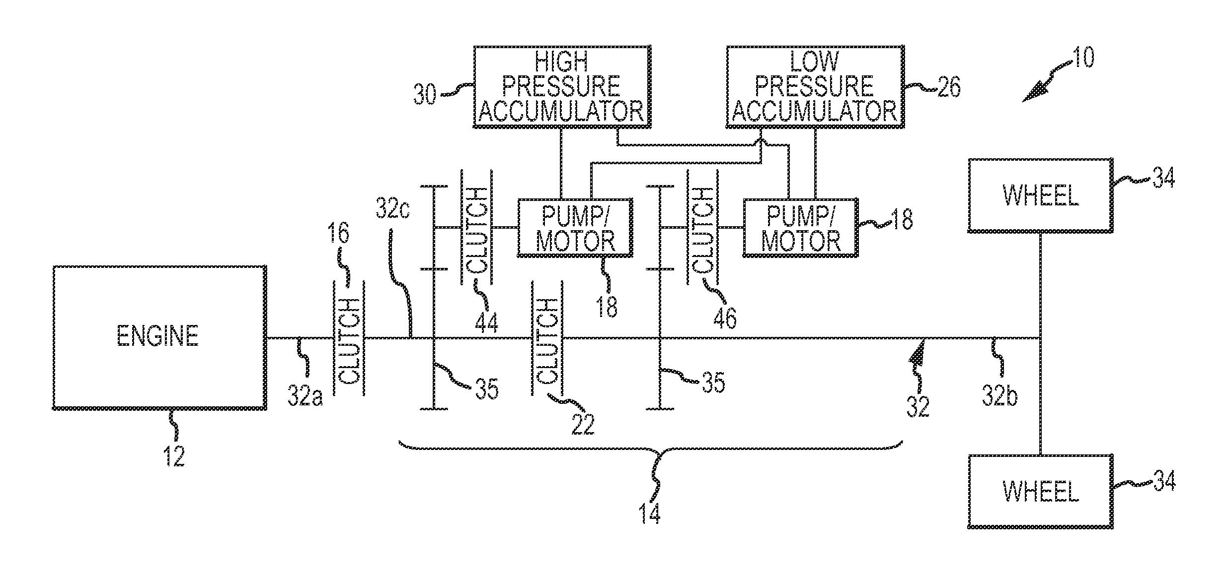
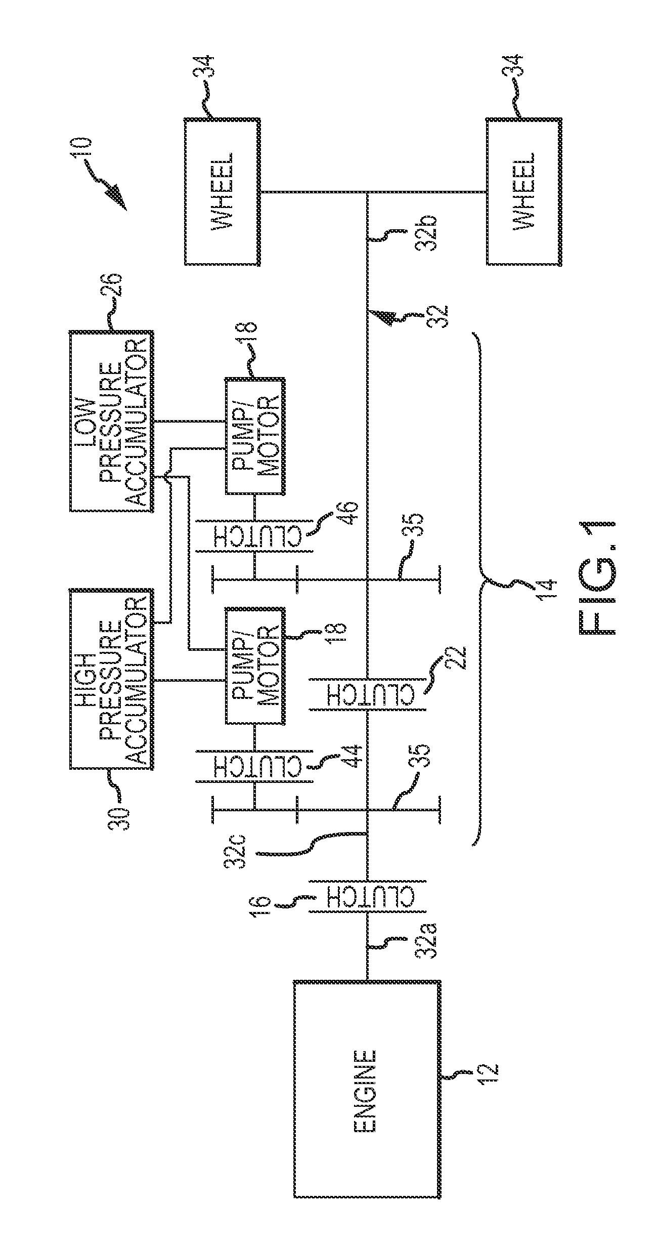
[0021]FIG. 1 is a representative diagram of a hybrid hydraulic drive system 10 according to one embodiment of the invention. In this embodiment, the inventive system 10 includes a novel arrangement of components that allows the system 10 to be dynamically configured to either transfer power solely through hydraulic system components (like a series hybrid hydraulic system) or to simultaneously transfer power through both mechanical and hydraulic paths (like a parallel hybrid hydraulic system). The system 10 also reduces cost and complexity via an operation and control process that requires fewer components than existing systems.

[0022]The system 10 includes an engine 12 that is coupled to a transmission unit 14 via a first clutch 16. The first clutch 16 may be a conventional dry clutch normally used in a manual gearbox, but connected to an electronic actuator so that the clutch 16 can be opened and closed automatically by an electronic control unit (not shown) with included control so...


PUM


Abstract

A vehicle drivetrain has a first driver, a first clutch to selectively couple the first driver with an engine, an energy storage device coupled to the first driver, a second driver coupled to the energy storage device and connected to a driveshaft, and a second clutch that selectively couples the first and second drivers. In one embodiment, the first clutch is opened and the second clutch is closed during a vehicle operating condition requiring high torque, the first clutch is closed and the second clutch is opened during a transient vehicle operating condition, and the first clutch and the second clutch are closed during a steady-state vehicle operating condition. Additional clutches may be included to reduce energy losses or provide multiple mechanical ratios. The drivers themselves may be pumps, motors, generators, combined pump / motors, or combined motor / generators, making the invention suitable for both hydraulic implementation and electric implementation.

Description

TECHNICAL FIELD [0001]The present invention relates to vehicle transmission systems, and more particularly to hybrid hydraulic drive system architectures.BACKGROUND OF THE INVENTION [0002]The motor vehicle industry is actively working to develop alternative powertrain systems in an effort to improve vehicle fuel economy and reduce the level of pollutants exhausted into the air by conventional drivetrain systems equipped with internal combustion engines. Significant development efforts have been directed to electric and fuel-cell vehicles as well as hybrid hydraulic vehicles.[0003]Unfortunately, these alternative drivetrain systems currently suffer from several limitations and, for all practical purposes, are still under development However, hybrid hydraulic and hybrid electric drivetrains have found success, particularly in vehicle applications with a lot of starting and stopping. Hydraulic drive systems facilitate conversion between mechanical energy (e.g., a mechanical output from...

Claims


Application Information

Patent Timeline
Patent Type & Authority Applications(United States)
IPC IPC(8): F16H59/00F16H3/08
CPCB60K6/12B60K6/442B60K2006/4833Y02T10/6282Y02T10/6208Y02T10/6234Y10T477/26Y10T74/19014Y10T477/32Y10T477/27Y10T74/19251Y10T74/19219Y02T10/92Y02T10/62
Inventor VAN BATAVIA, BRIAN L.MEEHAN, TIMOTHY I.OLSON, MICHAEL W.MAKIS, DAVID L.VOIGT, MICHAEL J.REMBA, DAVID S.DRAPER, DON R.
Owner EATON CORP
Why Eureka
Try Eureka