Valve

a valve and valve body technology, applied in the field of valves, can solve the problems of reducing the efficiency of the valve, reducing the safety of the valve, and not achieving the sealing of the mechanical components of the valve according to de 42 14 814 a1, so as to improve the safety against leakage, facilitate handling, and increase safety

Active Publication Date: 2013-03-21
MOKVELD VALVES BV
View PDF20 Cites 18 Cited by
  • Summary
  • Abstract
  • Description
  • Claims
  • Application Information

AI Technical Summary

Benefits of technology

[0016]Based on the known valves it is proposed according to the invention that the inner cavity of the actuator housing is separated from the fluid through a movable separation element. Thus, a penetration of fluid into the actuator, in particular between stator and moving element of the actuator is effectively prevented. Moving the separation element compensates volume changes in the interior. Such volume changes are caused, for example, by moving the spindle, by temperature changes, or by leakage of the dynamic seals between the inner cavity and the fluid. Using a pressure resistant, depending on the media, also media resistant stator and respective electrical connections facilitates omitting the divider wall between the stator and the moving element and thus facilitates a significantly increased efficiency of the actuator in particular for applications under high pressure.
[0037]Valves according to the invention facilitate handling in particular toxic fluids, thus fluids which are dangerous for the environment, humans or the climate not only in offshore oil and gas drilling, but, for example, also in petrochemical applications in nuclear facilities and in medical or pharmaceutical technology, for example, in hormone production. The complete integration of the actuator into the pressure loaded inner cavity of the valve improves safety against leakages and facilitates a significant extension of maintenance and replacement intervals.

Problems solved by technology

Eventually also any contact in particular of the electronics and of the mechanical components of the actuator with the drilled fluid is undesirable since it can be very aggressive due to contaminations with abrasive and corrosive components like sand, rust and in particular hydrogen sulfide.
In the latter case each increase of the gap between the stator and the moving element reduces the efficiency of the actuator.
On the other hand, the valve according to DE 42 14 814 A1 does not achieve any sealing of the mechanical components of the actuator against contaminants.

Method used


Image

  • Valve
  • Valve
  • Valve

Examples


Embodiment Construction

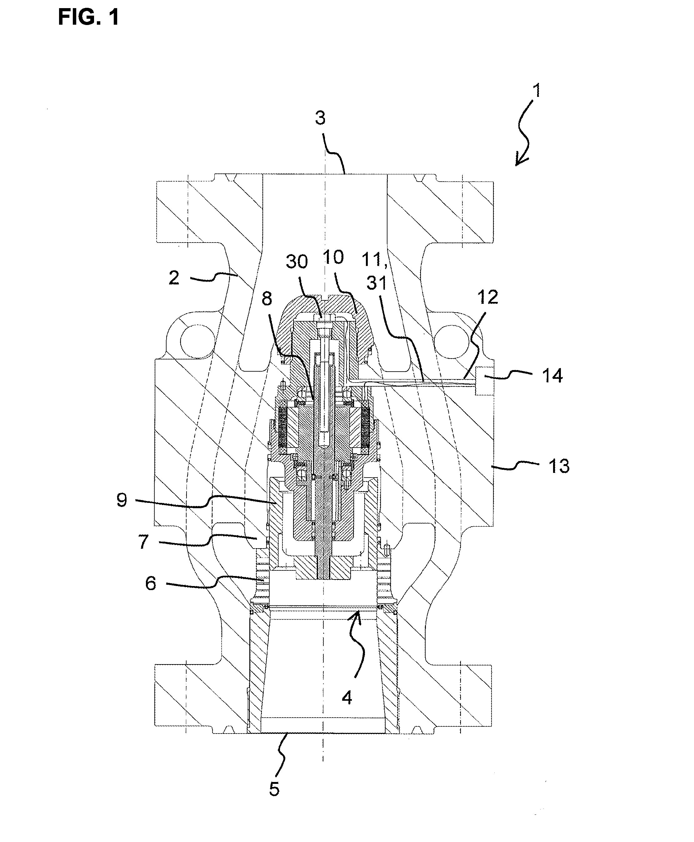
[0044]The valve 1 according to the invention illustrated in FIG. 1 is a throttle valve in an almost completely open position. It includes a housing 2 with an inlet opening 3 for a fluid which is not illustrated at a first pressure level, a throttle 4 for throttling to a second pressure level and an outlet opening 5 for the throttled fluid. The valve 1 can also be operated with an opposite flow direction from the outlet opening 5 to the inlet opening 3.

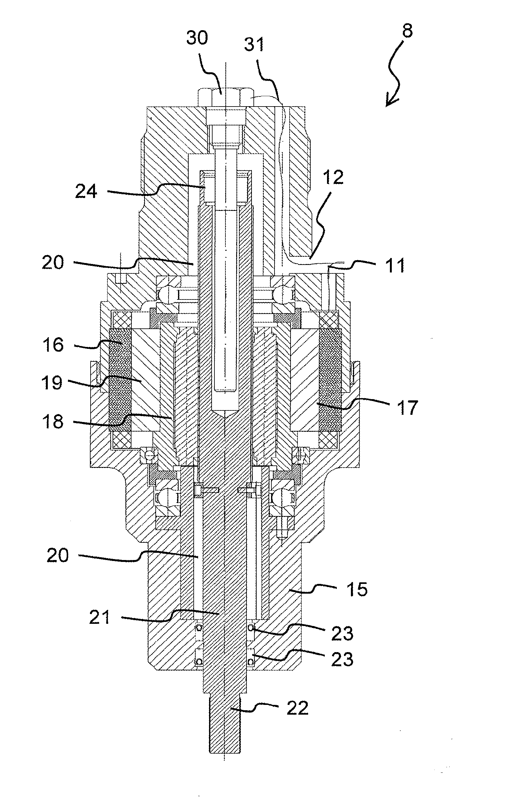
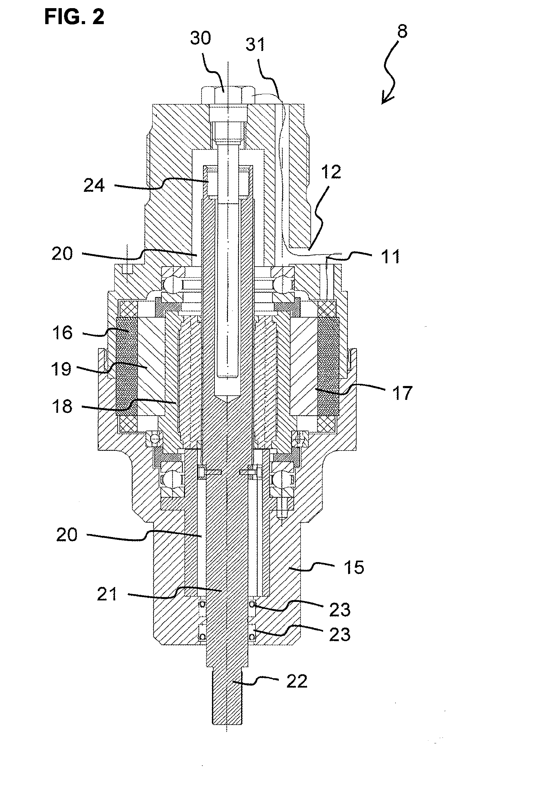
[0045]The throttle 4 is configured as a tubular throttle cage 6 between a tubular inner body 7 connected with the housing 2 and the outlet opening 5, wherein the tubular inner body is disposed in the flow path of the fluid. A piston shaped closure element 9 is axially moveable in the throttle cage 6 through an electric actuation device 8. Towards the inlet opening 3, the inner body 7 is closed with a closing cap 10 screwed onto the actuation device 8.

[0046]The connection conduit 11 of the actuation device 8 is run through a conductor c...


PUM


Abstract

A valve with a housing including an inlet opening and an outlet opening for a fluid; a closure element through which a flow of the fluid is controllable; an actuation device including an electric actuator for adjusting a closure cross section of the closure element; a drive housing at which a stator of the electric actuator is fixated, wherein a moveable moving element of the electric actuator is kinematically coupled with the closure element in an inner cavity of the drive housing which is loaded with a pressure from the fluid, wherein the stator is disposed in the inner cavity, and wherein the inner cavity of the drive housing is separated from the fluid through a moveable divider element. In order to use a valve with an actuator disposed in an abrasive fluid the inner cavity of the drive housing is separated from the fluid through a moveable divider element.

Description

RELATED APPLICATIONS[0001]This application is a continuation of International application PCT / EP2010 / 058005 filed on Jun. 8, 2010 claiming priority from German application DE 10 2009 026 838.3 filed on Jun. 9, 2009, both of which are incorporated in their entirety by this reference.FIELD OF THE INVENTION[0002]The invention relates to a valve with a housing including an inlet opening for a fluid, a closure element, through which a flow of the fluid is controllable, and an outlet opening for the fluid, and with a control device which includes an electric actuator for adjusting a closure cross section of the closure element, and with a drive housing, wherein a stator of the actuator is fixated to the drive housing, wherein a movable moving element of the actuator is coupled to the closure element in a kinematic manner and the stator is disposed within the inner cavity of the drive housing which is pressurized by a pressure of the fluid.[0003]DE 42 14 814 A1 discloses a flow control val...

Claims


Application Information

Patent Timeline
Patent Type & Authority Applications(United States)
IPC IPC(8): F16K31/04F16K37/00
CPCF16K1/12F16K31/04F16K37/00F16K31/047F16K47/08Y10T137/3367Y10T137/8225Y10T74/18576
Inventor ESVELDT, VINCENT
Owner MOKVELD VALVES BV
Why Eureka
Try Eureka