Method and device for image stabilization in an optical observation or measurement instrument

a technology of optical observation and measurement instruments, applied in the field of image stabilization in optical observation instruments or optical measurement instruments, can solve the problems of hand trembling, high problem, and blue recorded image, and achieve the effect of small control movement, small acceleration, and sufficient rapidity

Inactive Publication Date: 2013-03-21
CARL ZEISS MICROSCOPY GMBH
View PDF5 Cites 19 Cited by
  • Summary
  • Abstract
  • Description
  • Claims
  • Application Information

AI Technical Summary

Benefits of technology

[0025]The device according to the invention makes it possible to carry out the method according to the invention, and therefore to achieve the properties and advantages described in relation to the method according to the invention. Reference is therefore made to the properties and advantages described in relation to the method in order to avoid repetition.
[0026]In a specific configuration of the device according to the invention, the optical element with adjustable refractive power may comprise at least two freeform elements which can be moved relative to one another in a direction perpendicular to the optical axis. The at least one control signal represents in this case the position of the freeform elements perpendicularly to the optical axis. By a relative displacement of the two freeform elements, it is possible to adjust the refractive power of the optical element formed by the two freeform elements. Use of the freeform elements makes it possible to carry out the refractive power modifications which are necessary for compensating for the movement the between the observation optics and observation object, with very small control ...

Problems solved by technology

Movements of the observation optics which take place more rapidly than the imaging lead to blurring in the recorded image, which depending on the situation may be highly problematic.
Unintended movements of the observation optics may for example result from hand trembling in the case of hand-held observation and/or recording instruments, owing to which a stand is generally used for prolonged exposure times. Nevertheless, vibrations in mechanical holding devices of an optical observation instrument can also lead to blurring in the image.
When close objects are observed or recorded, for example with microscopes or macro-objectives, blurring in the image occurs not only because of movements of the observation optics perpendicular to the optical axis but also due to unintended movements parallel to the optical axis, i.e. in the direction towards the object and away from the object.
As a mechanical structure, however, the stand is not infinitely rigid and therefore exhibits a certain degree of deformation under loading.
Making the stand infinitely rigid is not technically possible.
Furthermore, a high rigidity also entails a ...

Method used


Image

  • Method and device for image stabilization in an optical observation or measurement instrument
  • Method and device for image stabilization in an optical observation or measurement instrument
  • Method and device for image stabilization in an optical observation or measurement instrument

Examples


Embodiment Construction

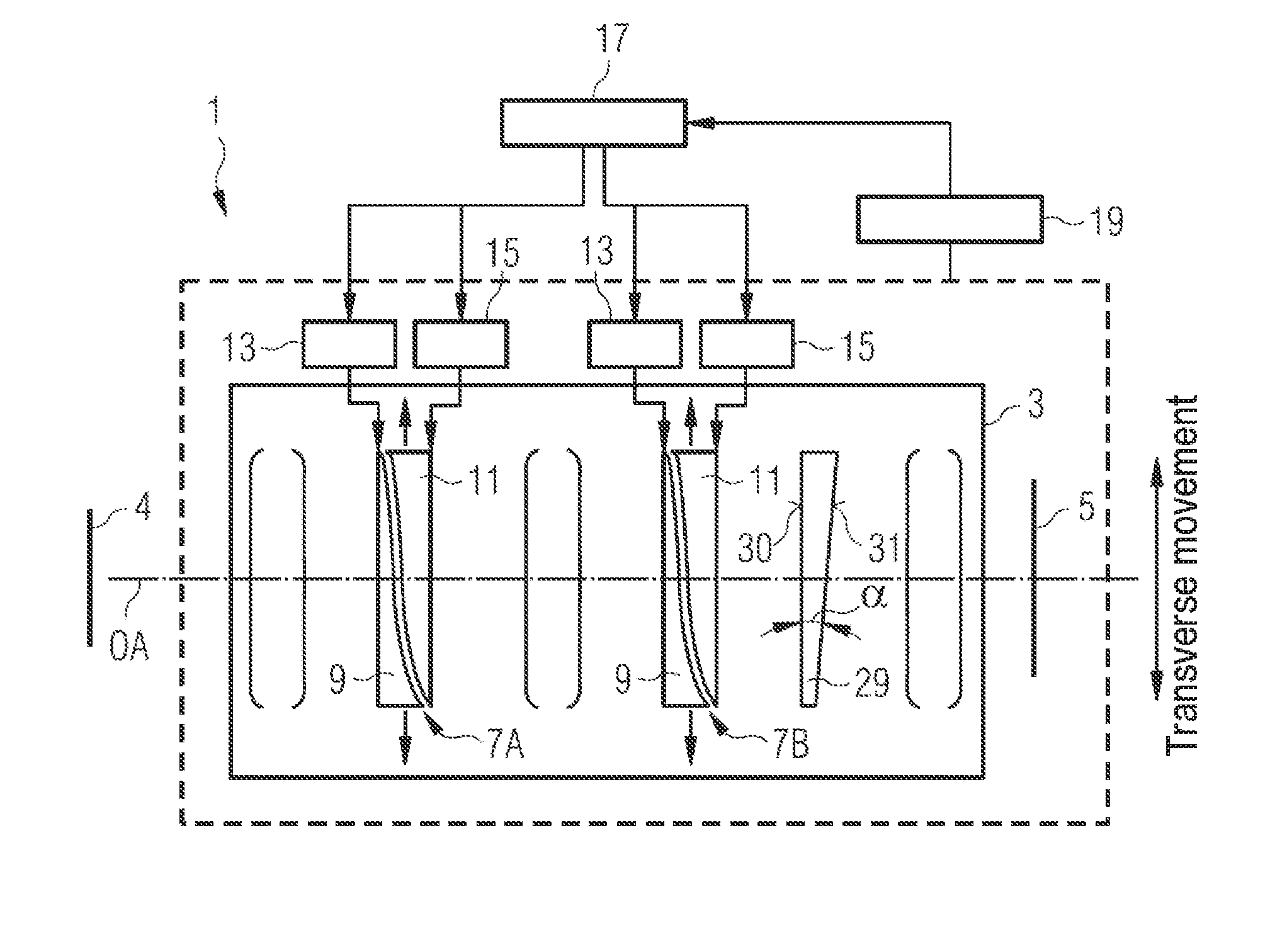
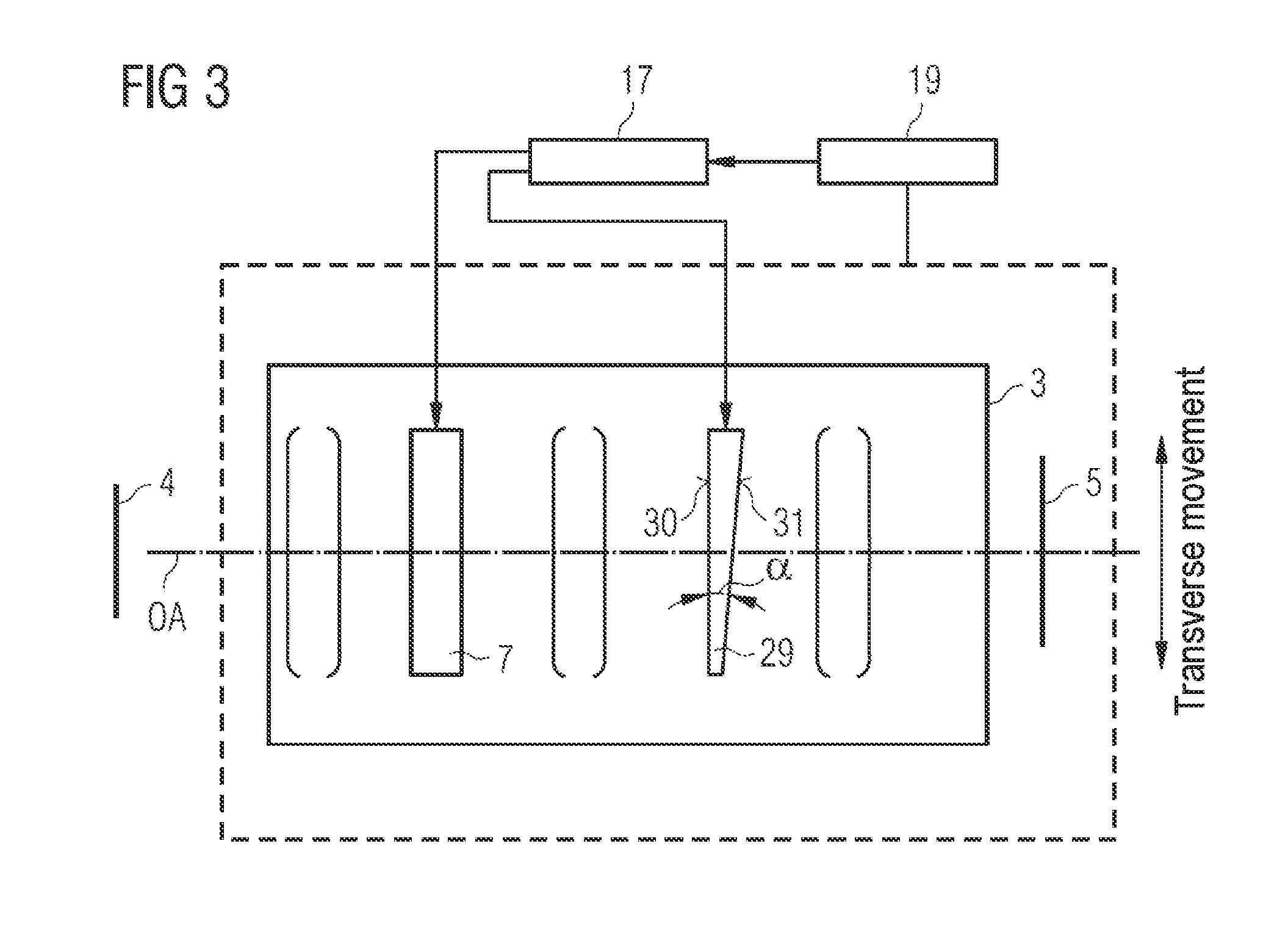
[0038]A first exemplary embodiment of an optical observation instrument according to the invention will be described below with reference to FIG. 1. The figure shows in a highly schematized way a camera comprising a macro-objective 3 as observation optics and an image sensor 5, onto which the observation object 4 is imaged with the aid of the macro-objective 3. The camera 1 furthermore comprises an image stabilization device, with which unintended movements between the camera 1—and therefore the macro-objective 3—on the one hand and the observation object 4 on the other hand along the optical axis OA of the objective can be optically compensated for, i.e. compensated for by optical means. Movements to be compensated for may for example be caused by hand trembling or, if the camera 1 is mounted on a stand, by stand vibrations. It is, however, also possible to compensate for movements of the observation object 4.

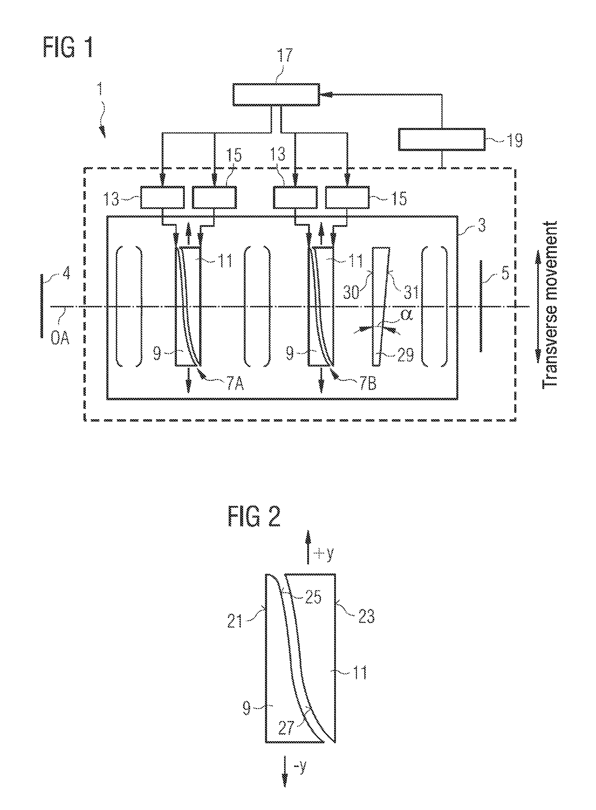
[0039]The image stabilization device comprises an optical element with ad...


PUM


Abstract

A method is provided for image stabilization in an optical instrument (1, 101) with observation optics (3) that have an optical axis (OA) and at least one optical element with adjustable refractive power (7, 7A, 7B, 177), an unintended movement taking place between the observation optics (3) and an observation object (4) along the optical axis (OA). The unintended movement along the optical axis (OA) is determined and on the basis of the movement determined, at least one control variable for the adjustable optical element (7, 7A, 7B, 177) is determined, which represents the refractive power of the optical element with adjustable refractive power (7, 7A, 7B, 177) necessary for optical compensation for the movement along the optical axis (OA). An adjustment of the optical element with adjustable refractive power (7, 7A, 7B, 177) is carried out on the basis of the control variable.

Description

BACKGROUND OF THE INVENTION[0001]1. Field of the Invention[0002]The present invention relates to a method for image stabilization in an optical observation instrument or an optical measurement instrument comprising observation optics, which are subject to movement along their optical axis. The invention furthermore relates to a device for image stabilization in an optical observation instrument or an optical measurement instrument. The invention furthermore relates to an optical observation or measurement instrument.[0003]2. Description of the Related Art[0004]During the observation of observation objects by means of optical observation instruments, the observation object must be kept stationary in order to avoid blurring in the images. This applies in particular when electronic imaging is intended to be carried out with the optical observation instrument. Movements of the observation optics which take place more rapidly than the imaging lead to blurring in the recorded image, which...

Claims


Application Information

Patent Timeline
IPC IPC(8): G02B27/64
CPCG02B27/64G02B21/22G02B21/0012
Inventor PRETORIUS, MARCO
Owner CARL ZEISS MICROSCOPY GMBH
Why Eureka
Try Eureka