
Wireless communication system and method for performing handover in such a system

Active Publication Date: 2013-03-21
SAMSUNG ELECTRONICS CO LTD
View PDF3 Cites 44 Cited by
  • Summary
  • Abstract
  • Description
  • Claims
  • Application Information

AI Technical Summary

Benefits of technology

The patent text describes a method to reduce the load on the main network device (MME) and the communication link between the eNB gateway and the MME during a handover between eNBs. This is achieved by controlling the handover and blocking the transmission of handover-related messages to the MME. The technical effect of this method is improved network performance and reduced network load.

Problems solved by technology

However, the mobile communication systems face resource shortage and user requirements for speed service and thus there is a need of more advanced mobile communication system.
Nevertheless, since the increase in number of terminals (User Equipment, UE) served by a base station increases and thus sharing the resource causes resource shortage, each UE may be served at very low data rate even though the system actually supports high packet transmission service.

Method used


Image

  • Wireless communication system and method for performing handover in such a system
  • Wireless communication system and method for performing handover in such a system
  • Wireless communication system and method for performing handover in such a system

Examples


first embodiment

[0063]FIG. 7 is a signal flow diagram illustrating the handover procedure with the eNB gateway according to the present invention.

[0064]FIG. 7 is directed to the case where the eNB gateway 604 saves the UE-related security information list in the handover of the UE 700 from the eNB 702 (hereinafter, referred to as eNB1) not connected to the eNB gateway 706 to the eNB 704 (hereinafter, referred to as eNB2) connected to the eNB gateway 604.

[0065]Referring to FIG. 7, the UE 700 and eNB1702 are in communication using KeNB1 and NCC=1 at step 710. At this time, the eNB1702 saves NH and NCC=2 at step 712. Next, the eNB1702 makes a handover decision according to the change of the location of the UE 700 at step 714. The eNB1702 selects the eNB2704 as the target eNB and then generates KeNB2 in consideration of the NH value saved at step 712 and the cell information (Physical cell ID and downlink frequency information) of the eNB2704.

[0066]The eNB 702 sends the eNB2704 a Handover Request messa...

second embodiment

[0071]FIG. 8 is a signal flow diagram illustrating a handover procedure with the eNB gateway according to the present invention.

[0072]FIG. 8 is directed to the case where tin UE handover-related message is processed by the eNB gateway 806 without delivery to the MME in the handover occurring from an eNB 802 (hereinafter, referred to as eNB2) connected to the eNB gateway 806 to another eNB 804 (hereinafter, referred to as eNB3) connected to the eNB gateway 806.

[0073]Referring to FIG. 8, the eNB gateway 806 saves the list of NH and NCC values as the UE security information transmitted by the MME at step 808. Afterward, the UE 800 and the eNB2802 perform secured communication using KeNB2 and NCC=2 at step 810. At this time, the eNB2802 saves the NH and NCC=3 transmitted by the eNB gateway 806 as described with reference to step 740 of FIG. 7 at step 812.

[0074]The eNBs 802 makes a handover decision for the UE 800 according to the movement of the UE 800 at step 814. Next, the eNB2802 sel...

third embodiment

[0082]FIG. 10 is a signal flow diagram illustrating the handover procedure with the eNB gateway according to the present invention.

[0083]FIG. 10 is directed to the case where the eNB gateway 1006 saves the UE-related security information list when the handover of the UE 1000 occurs from the eNB 1002 (hereinafter, referred to as eNB1) not connected to the eNB gateway 1006 to an eNB 1004 (hereinafter, referred to as eNB2) connected to the eNB gateway 1006.

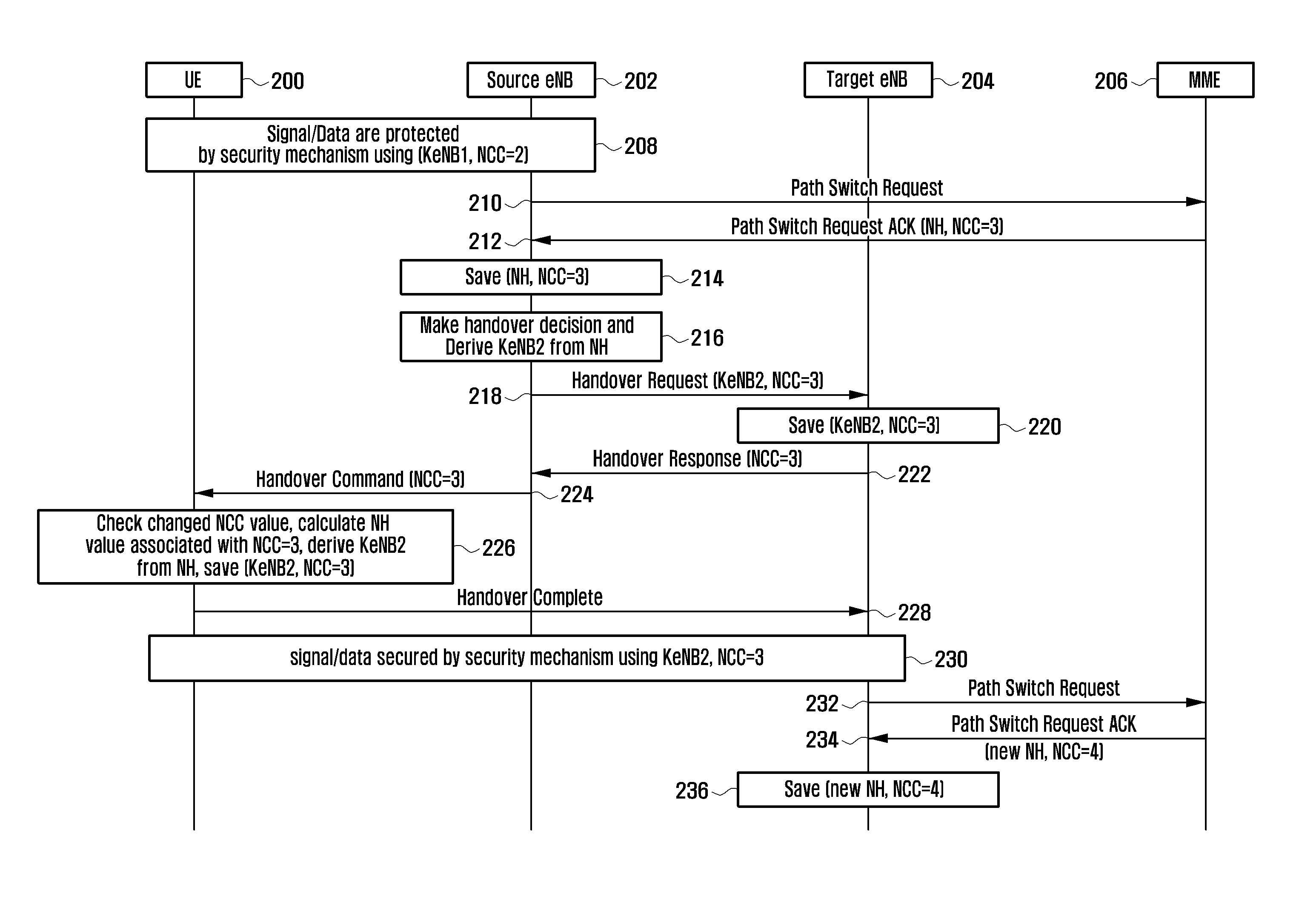
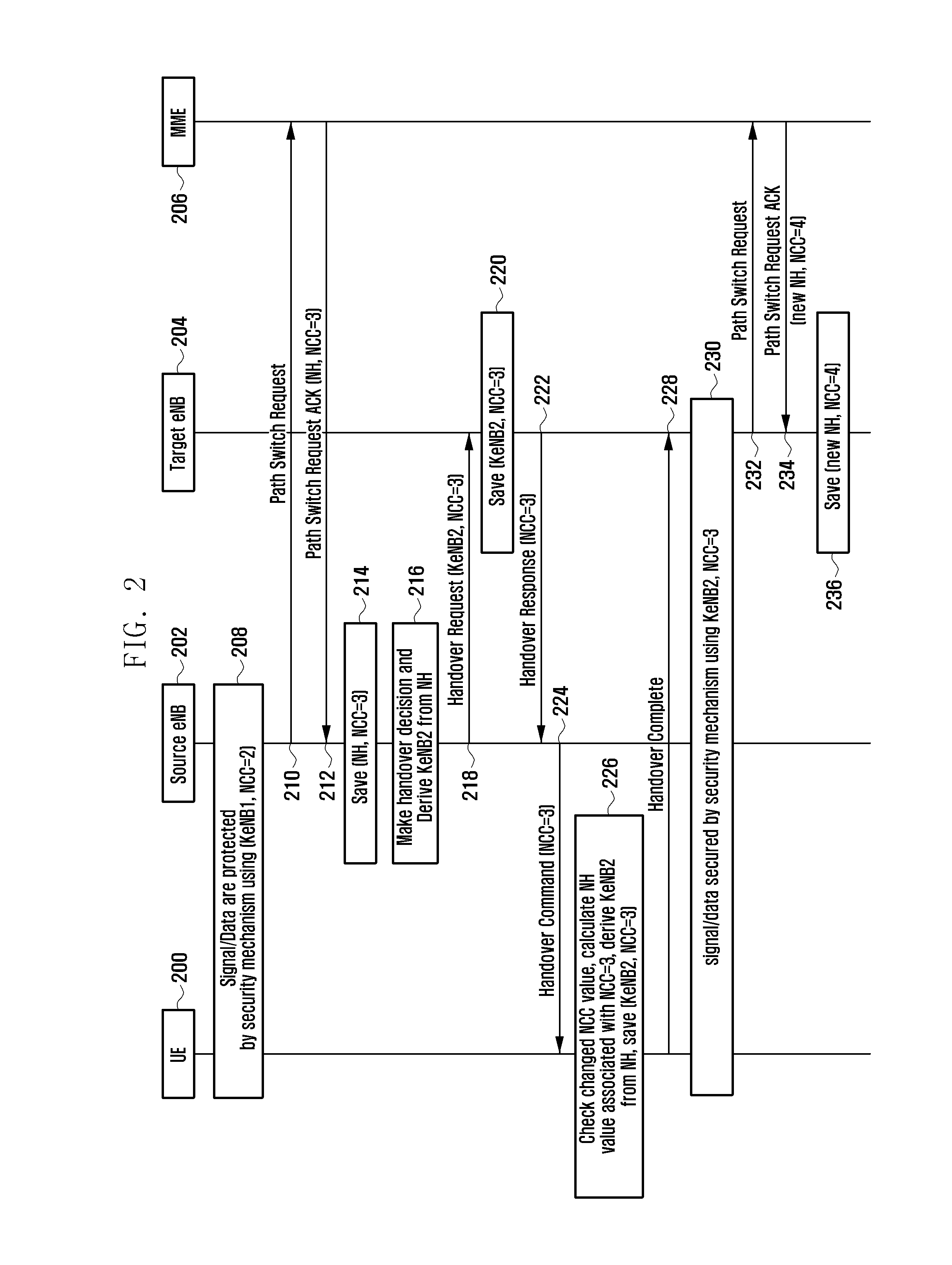
[0084]Referring to FIG. 10, the UE 1000 and eNB11002 are performing secured communication using KeNB1 and NCC=1 at step 1010. The eNB11002 saves, at step 1012, the NH and NCC values transmitted by the eNB gateway as described with reference to step 236 of FIG. 2 and step 418 of FIG. 4. Here, the description is made under the assumption that the NNC transmitted by the eNB gateway is set to 2.

[0085]The eNB11002 makes a handover decision for the UE 1000 according to the location change of the UE 1000 at step 1014. At this time, the eNB1...


PUM


Abstract

The present invention relates to a method and apparatus for performing handover in a wireless communication system, and the handover method of the present invention includes checking, when a Path Switch Request message associated with a terminal is received from a base station, whether a list of terminal security information values which has been saved exists; generating, when the list exists, a Path Switch Request acknowledge message including an unused terminal security information value selected form the list; and transmitting the Path Switch Request acknowledge message to the base station. Through this procedure, it is possible to reduce the terminal handover signal load generated by the base station.

Description

BACKGROUND OF THE INVENTION[0001]1. Field of the Invention[0002]The present invention relates to a method and apparatus for performing handover in a wireless communication system. In particular, the present invention relates to a method and apparatus for reducing the load of handover signals generated in the handover of a terminal.[0003]2. Description of the Related Art[0004]Mobile communication systems have developed to provide the subscribers with voice communication services on the move. With the advance of technologies, the mobile communication systems have been evolved to support high speed data communication services as well as the standard voice communication services. However, the mobile communication systems face resource shortage and user requirements for speed service and thus there is a need of more advanced mobile communication system.[0005]In order to accomplish the requirements, the 3rd Generation Partnership Project (3GPP) is standardizing Long Term Evolution (LTE) a...

Claims


Application Information

Patent Timeline
IPC IPC(8): H04W36/00
CPCH04W28/10H04W36/00H04W12/04H04W88/16H04W36/0038H04W88/08H04W12/043H04W12/041H04W12/08H04W36/12H04W36/165
Inventor LIM, CHAE GWONCHO, SONG YEANCHOI, SUNG HOBAE, BEOM SIKLIM, HAN NA
Owner SAMSUNG ELECTRONICS CO LTD
Features
  • Generate Ideas
  • Intellectual Property
  • Life Sciences
  • Materials
  • Tech Scout
  • Unparalleled Data Quality
  • Higher Quality Content
  • 60% Fewer Hallucinations
Learn More