Reinforced Suture Strip and Methods of Use

a technology of reinforced suture and suture strip, which is applied in the field of reinforced suture strip and methods of use, can solve the problems of increased risk of infection in open wounds, increased likelihood of substantial scar tissue and later visible scarring, and increased scarring degree, so as to prevent suture stretching, avoid infection of wounds, and prevent any widening of incisions

Inactive Publication Date: 2013-03-21
WEBTEC CONVERTING
View PDF4 Cites 1 Cited by
  • Summary
  • Abstract
  • Description
  • Claims
  • Application Information

AI Technical Summary

Benefits of technology

[0011]By substantially immobilizing the two areas of skin tissue on opposing sides of an incisive wound, the reinforced suture strip helps to keep abutting skin tissue on opposing sides of the incisive wound from sliding or separating with respect to each other. By substantially immobilizing the two areas of skin tissue on opposing sides of an incisive wound, the reinforced suture strip helps to prevent suture stretching and helps to prevent any widening of an incision of reopening of a wound that has begin to close. Preventing reopening of the wound helps to avoid infection of the wound or the entry of foreign biological and non-biological entities. Further, by substantially immobilizing the skin tissue around an incisive wound, the reinforced suture strip facilitates the formation of linkages between areas of skin tissue on opposing sides of the incisive wound, hastening the healing process and helping to minimize the development of scar tissue and the appearance of scars.
[0012]Some embodiments of the present invention include methods and processes in which a reinforced suture strip is combined with an angled incision or angled incisive wound so as to reduce the appearance of scars from incisions. In some circumstances, such as surgery, it is necessary for a medical practitioner to make an incision in the patient's skin. If the incision made is a vertical incision—i.e., the main direction of the incision is substantially perpendicular to the plane of the patient's top-most layer of skin—then, during the healing process, the areas of skin on opposing sides of the incision must form fibrous cross-linkages in a largely horizontal direction—that is, substantially parallel to the top-most layer of skin. Because the separated areas of skin on opposing sides of the incision will also likely be pulled and moved in a largely horizontal direction during the healing process, the body's healing process must work almost directly against the expected movement of the separated areas of skin. On the other hand, if the incision is made angled—that is, the angle of incision is substantially acute with respect to the plane of the top-most layer of skin—then, during the healing process, the areas of skin on opposing sides of the incision will form fibrous cross-linkages in substantially angled and vertical directions, without directly competing with the horizontal movement of the separated opposing areas of skin on either side of the incision. A reinforced suture strip further enhances and supplements the beneficial aspects of the angled incision or angled incisive wound. By substantially immobilizing the two areas of skin tissue on opposing sides of the angled incisive wound, the reinforced suture strip helps to keep abutting skin tissue on opposing sides of the angled incisive wound from sliding or separating with respect to each other. In some embodiments, the reinforced suture strip is used to supplement the wound-closing action of a conventional suture after the wound has been sutured.

Problems solved by technology

Reopening of the wound delays the healing process and also increases the likelihood for the appearance of substantial scar tissue and later visible scarring.
Additionally, an open wound is at a heightened risk of infection throughout the healing process.
With the exception of very minor lesions, skin wounds following accidents, disease or surgery all result in some degree of visible scarring.
Where the scar tissue is large or in a prominent position on the body, it can be readily apparent to a casual observer and embarrassing or otherwise troubling for the scarred person.

Method used


Image

  • Reinforced Suture Strip and Methods of Use
  • Reinforced Suture Strip and Methods of Use
  • Reinforced Suture Strip and Methods of Use

Examples


Embodiment Construction

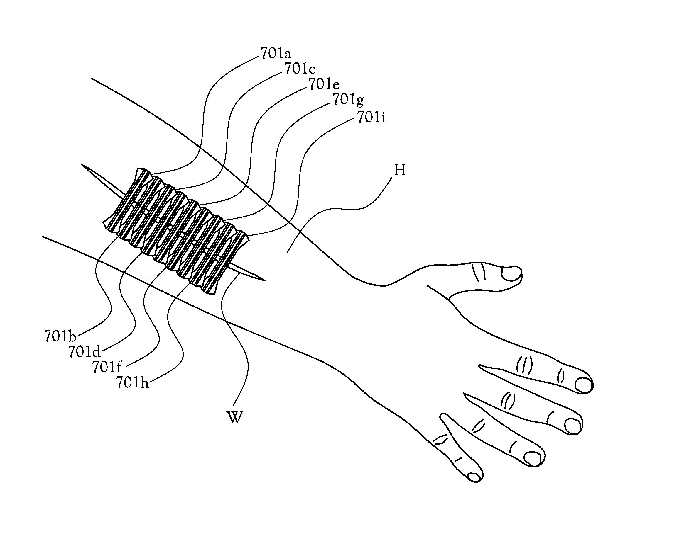
[0021]The present invention in some of its embodiments is directed toward a reinforced suture strip that incorporates resilient bands oriented parallel to one another along a longitudinal axis of the suture strip. In some of its embodiments, the reinforced suture strip inhibits or minimizes both abductive and transverse movement by the opposing sides of flesh about an incisive wound. The present invention also comprises in some of its embodiments methods and processes for treating wounds using reinforced suture strips as described herein.

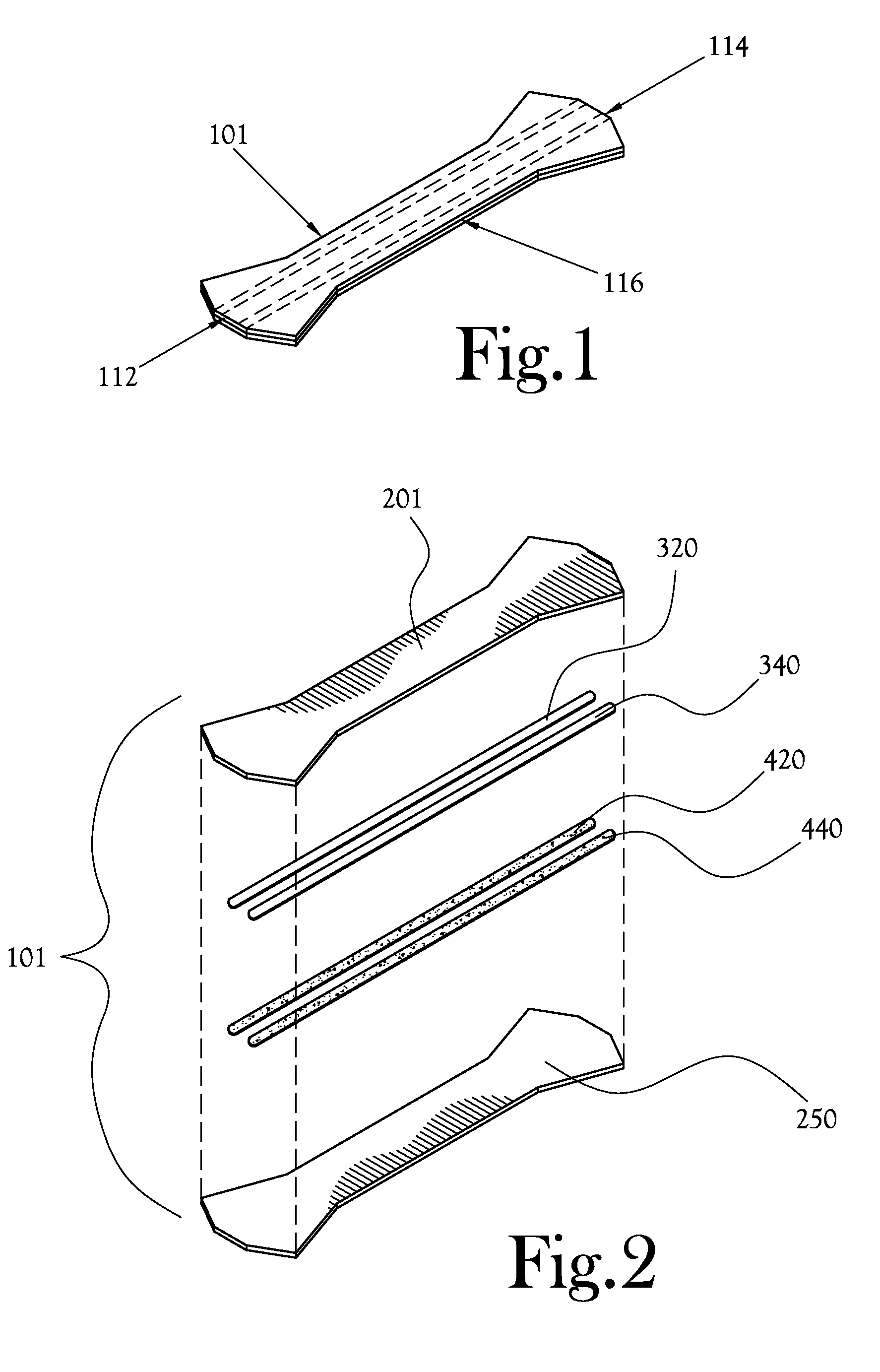
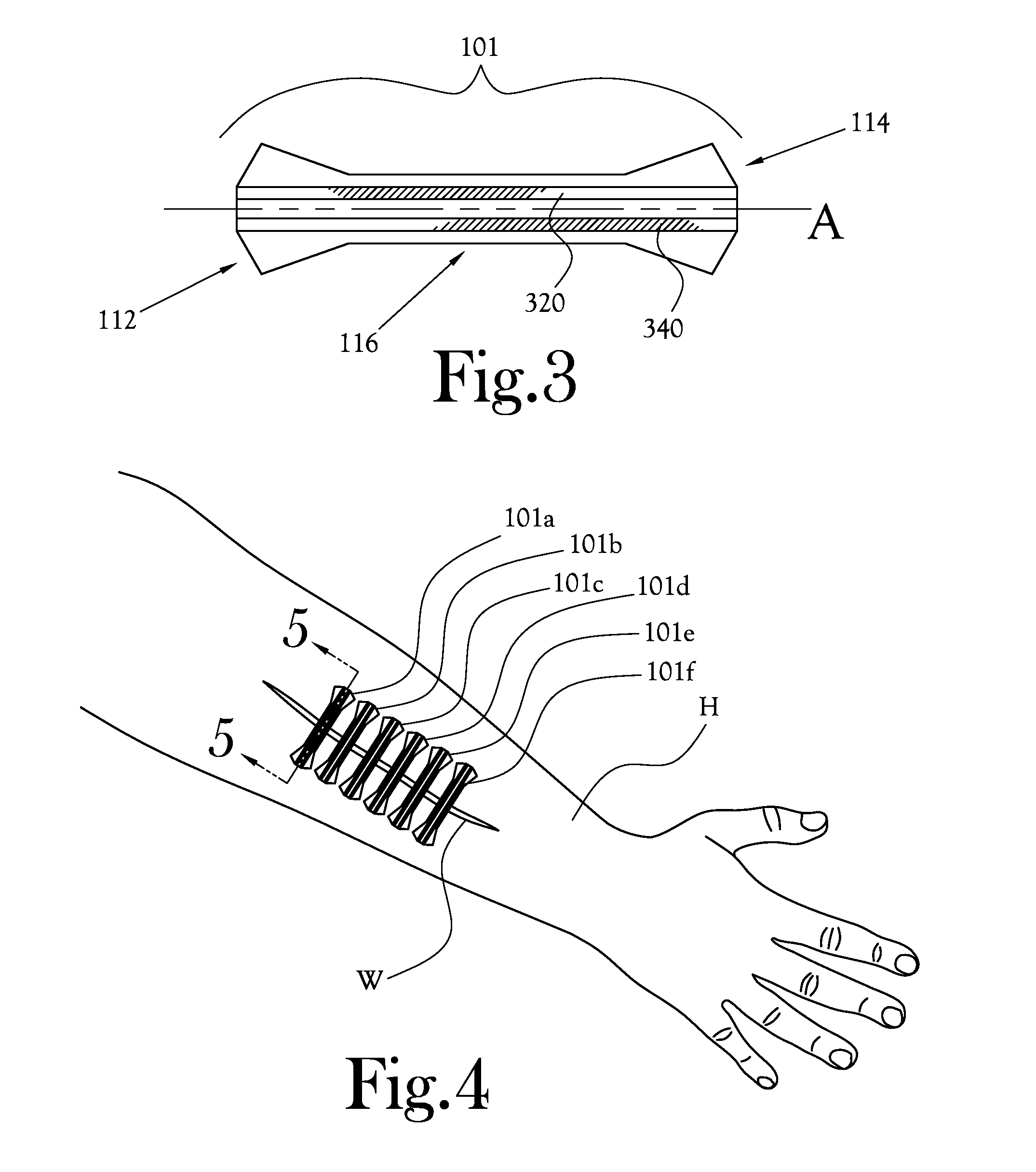
[0022]FIG. 1 is a perspective view of one example embodiment of a reinforced suture strip according to the present invention. As shown in FIG. 1, a suture strip 101 includes a length of material comprising a two end regions 112 and 114 and a middle region 116; generally, the middle region 116 is narrower at its narrowest point than the width of the two end regions 112 and 114 at their widest points. The reinforced suture strip 101 is applied to the ...


PUM


Abstract

A reinforced suture strip that incorporates resilient bands oriented parallel to one another along a longitudinal axis of the suture strip. Each band includes a semirigid strip of resilient material, said strip generally extending substantially the length of the suture strip, substantially parallel to the longitudinal axis of the suture strip. The reinforced suture strip inhibits or minimizes both abductive and transverse movement by the opposing sides of flesh about an incisive wound. The present invention also comprises in some of its embodiments methods and processes for treating wounds using reinforced suture strips as described herein.

Description

CROSS-REFERENCE TO RELATED APPLICATIONS[0001]Not ApplicableSTATEMENT REGARDING FEDERALLY SPONSORED RESEARCH OR DEVELOPMENT[0002]Not ApplicableBACKGROUND OF THE INVENTION[0003]1. Field of Invention The present invention relates generally to methods and devices used to close a wound or to tie bind or constrict a portion of a body and in particular to the use of suture strips to prevent suture stretching, encourage the formation of fibrous cross-linkages, and reduce widening of an incision, thereby inhibiting scar formation, reopening of a wound, and infection.[0004]2. Description of the Related Art[0005]In order for incisions or incision-based wounds to heal, it is frequently necessary to immobilize the areas of skin on opposing sides of an incision or incision-based wound with respect to the incision or incision-based wound, so that abutting areas of skin tissue on opposing sides of the incisive wound do not slide or separate with respect to each other. Hereinafter, “incisive wounds”...

Claims


Application Information

Patent Timeline
Patent Type & Authority Applications(United States)
IPC IPC(8): A61B17/03
CPCA61B17/085A61B2017/00831A61F2013/00455A61B2017/086A61B2017/0495
Inventor MCCLURE, JR., ROBERT L.CUNNINGHAM, KELLIEHOLMES, RANDEL B.
Owner WEBTEC CONVERTING
Why Eureka
Try Eureka