Storage apparatus, computer system, and data migration method

Inactive Publication Date: 2013-03-21
HITACHI LTD
View PDF4 Cites 24 Cited by
  • Summary
  • Abstract
  • Description
  • Claims
  • Application Information

AI Technical Summary

Benefits of technology

[0020]According to the storage apparatus of the present invention, data can be migrated chunk-by-chunk by dividing a storage extent in the second storage unit into chunks and dynamically allocat

Problems solved by technology

However, accesses to the data volumes may not be homogenous in all areas in the data volumes.
As a result, data with low access frequency

Method used


Image

  • Storage apparatus, computer system, and data migration method
  • Storage apparatus, computer system, and data migration method
  • Storage apparatus, computer system, and data migration method

Examples


first embodiment

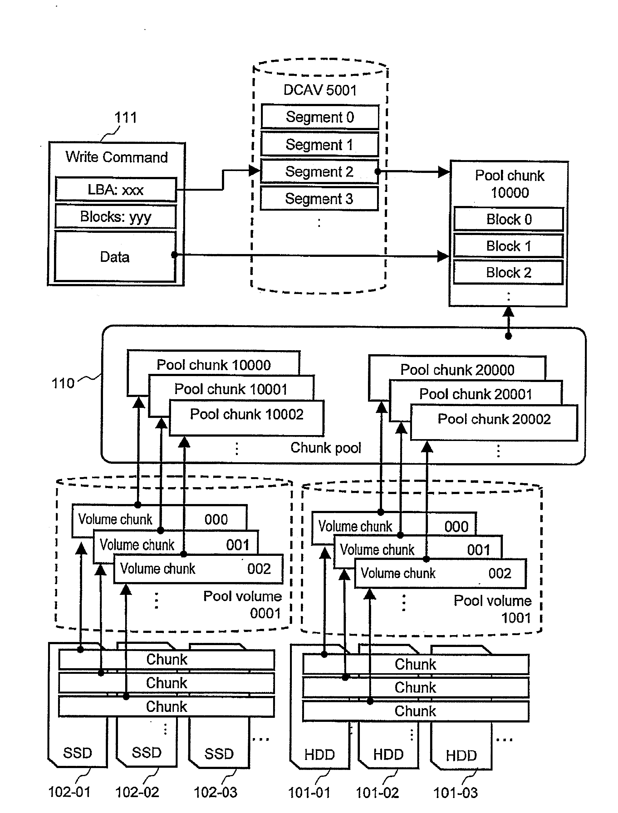
[0198]As described, according to the present first embodiment, a data volume, in which data is stored and the dynamic chunk allocation function cannot be used, can be used to create a DCAV storing the same content without migrating the data. As a result, necessary data in the data volume can be migrated chunk-by-chunk as necessary between storage apparatuses. Therefore, compared to a method of creating a copy of a data volume to migrate data between storage apparatuses, the storage capacity can be efficiently improved, and the communication band between storage apparatuses necessary for the data migration can be reduced.

[0199]According to the present first embodiment, existing data volumes created from physical storage devices with uniform performances can be converted to DCAVs while maintaining the contents, and physical storage extents with performances corresponding to the use frequencies can be allocated chunk-by-chunk. As a result, the cost performance of the data volumes can b...

second embodiment

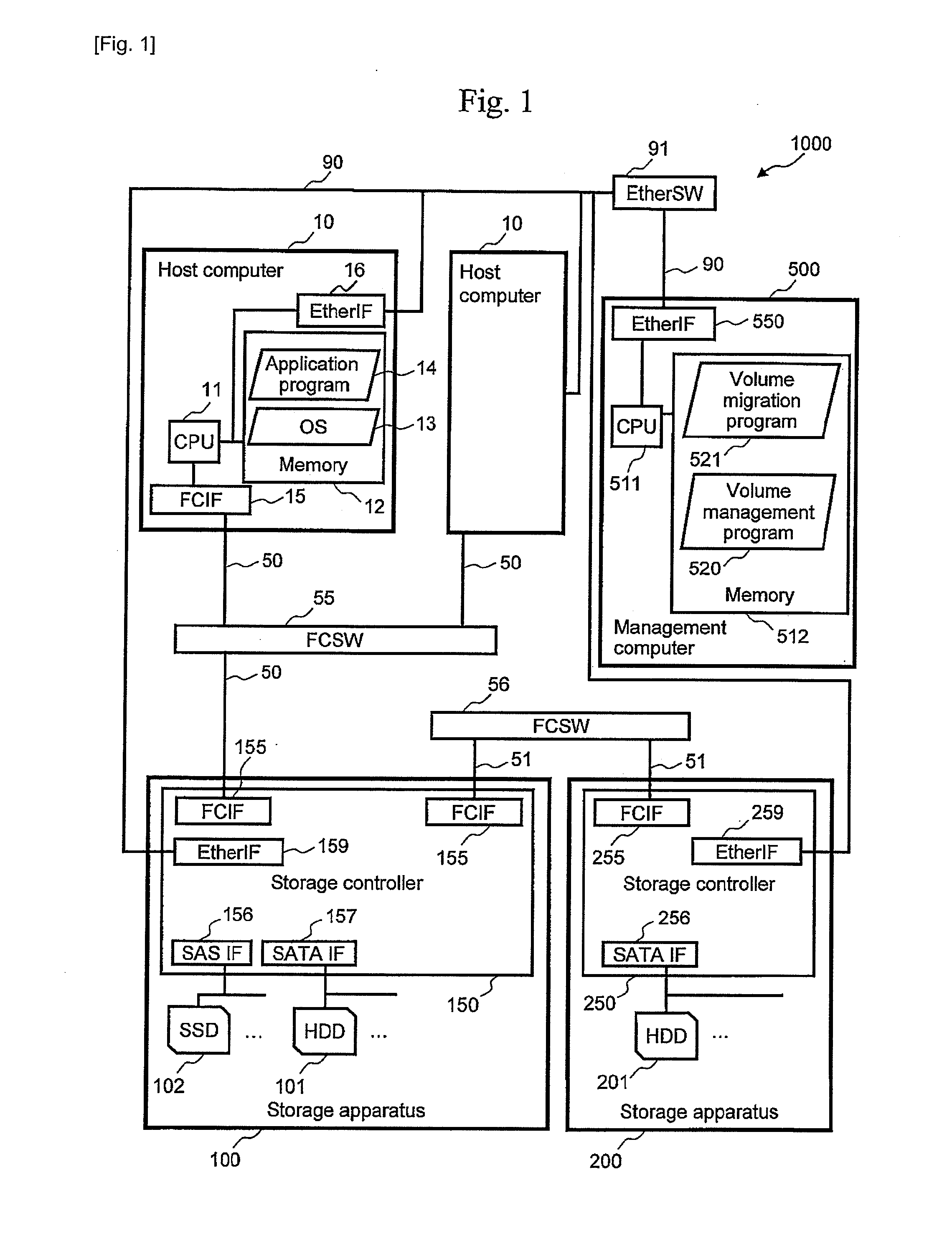
[0201]Although an example of migrating data from the second storage apparatus 200 connected outside the first storage apparatus 100 has been described in the first embodiment, a similar method can also be applied to the data volumes in the first storage apparatus 100. An example of the operation will be described in a second embodiment of the present invention.

[0202]FIG. 19 is a diagram showing a logical configuration of the storage extent in the first storage apparatus 100 according to the present second embodiment. In the present second embodiment, the data volume 113 in the first storage apparatus 100 is a target of data migration.

[0203]A procedure of migrating the data in the data volume 113 to another pool volume by converting the target data volume 113 to the DCAV 5002 is the same as in the first embodiment except that the data volume 113 is the target instead of the data volume 112. More specifically, except the point that the data volume 113 is not created by the external st...

third embodiment

[0240]As described, according to the present third embodiment, only the virtual disk constituting the VM 20 in use can be selectively migrated when the virtual disk constituting the VM 20 in use and the virtual disk constituting the VM 20 not in use are arranged on the same data volume.

[0241]According to the present third embodiment, the storage extent satisfying the required performance can be allocated to each VM 20 to start the use without waiting for the completion of the migration of all VMs 20 in the same data volume.

[0242]According to the present third embodiment, only a specific area can be selectively migrated within the same virtual disk chunk-by-chunk. In the migration of the VM 20, the virtual disk (image file) can be divided into chunks, and the virtual disk can be efficiently migrated in more detail in accordance with the access pattern to the virtual disk.


PUM


Abstract

Provided is a method of using a dynamic chunk allocation function to efficiently carry out data volume migration. A storage apparatus according to the present invention includes first and second storage units and divides a storage extent in the second storage unit into chunks to add the chunks to a chunk pool to dynamically allocate the chunks in the chunk pool to a newly created logical data volume (see FIG. 3).

Description

TECHNICAL FIELD [0001]The present invention relates to a storage apparatus.BACKGROUND ART [0002]Storage extents in a storage system are provided to a host computer as a logical set called data volumes. The host computer recognizes the data volumes as one logical device. Conventionally, the data volumes are created from one large set (for example, a RAID group) of physical storage devices (for example, magnetic hard disk drives). Therefore, storage extents with homogenous physical characteristics (I / O performance and cost) are allocated to the data volumes.[0003]However, accesses to the data volumes may not be homogenous in all areas in the data volumes. For example, when a server virtualization technique is used to construct an information system, a plurality of virtual disks with significantly different access frequencies due to the roles or applications of the virtual machines may be stored in the same data volume.[0004]As a result, data with low access frequency is continuously ...

Claims


Application Information

Patent Timeline
IPC IPC(8): G06F12/02G06F12/08
CPCG06F3/0607G06F3/0617G06F3/0647G06F3/0664G06F12/08G06F3/067G06F3/0644G06F3/0646G06F12/02G06F3/0665
Inventor TERAYAMA, ATSUMINAGAMI, AKIHISATANAKA, TORUKANEDA, YASUNORI
Owner HITACHI LTD
Why Eureka
Try Eureka